Timber Framers Guild

Compass

Posted By: D L Bahler

Compass - 02/25/11 02:51 AM


This is a picture of a medieval master mason, likely the chief architect of a cathedral, with a very important tool in the practice of medieval architecture, the large 'outdoor compass'


Another picture from a 14th century manuscript, depicting a king with his chief architect.

The giant compass is used to transfer measurements from the architect's plans to full scale at the building site. The procedure here seems to have been to take a few key measurements from the drawings with the small drawing compass, and set the the large compass to several times the opening size of the smaller one, which is then swung a number of times to yield the final measurement.
To do this you need a scale, say 1:150, this is the scale of the drawing. You then need to take two factors of this number, say 15 and 10. To get the full scale measurement, you might first use the small compass to make a line 15 times the size of the original on the drawing, then set the large compass to this size and swing it out 10 times to yield the full sized line. This procedure is subject to slight inaccuracies on the order of perhaps an inch or two in 50 feet.

Now I have this on the tool forum, because I have a question.

I wonder if it would be possible for me to obtain, or else have made, a giant compass such as this.

The following can be observed about its construction:

They are generally somewhere around 3 feet in height, made of metal (presumably steel)
They have at least 1 retaining arc to help hold their positioning, whereas contemporary drawing compasses generally had no retaining arcs. These arcs are necessary to keep the compass in perfect alignment as the weight of the legs would be too much for a set screw at the joint to handle.

It seems that the retaining arcs worked by means of a light hammer tap, by which they were driven into wedged openings and thus held the alignment by friction. Or alternately they may have been held into position by driving a wedge into the openings in the legs that they passed through. Perhaps a modern version could work adequately with set screws rather than wedging.
I would like to have such a tool because I think it would be very useful to me, and easier to use than a rope compass.
Posted By: mo

Re: Compass - 02/25/11 03:20 AM

Hi DL, How bout some trammel points? You sure do like to step things off.

Or you could make huge proportional dividers.


1/15:1 Step off ten times. By the way these dividers are really quite neat for proportional design work. Oh yea and really quite expensive too.
Posted By: D L Bahler

Re: Compass - 02/25/11 04:24 AM

The large compass has the big advantage of allowing you to stand up while using them. And most of all to me they are of great historical interest.

The method described is how it is thought they built churches and cathedrals, among other things, in the Middle Ages. The documentary evidence certainly suggests it, as does the mensural evidence. The system works, and works quite well. It gives the architect the means of scaling up his plans to create the building. This is important because it makes so that he knows his drawing will meet the specifications of the job.

What would have been done is that the person ordering a building would specify one specific measurement for a certain dimension of the building, in the case of a church or cathedral this usually meant that some important measurement such as the length of the nave was equal to 153 feet, 153 feet being the number of fish in Peter's net. The architect could then set that measurement on his drawing to something proportionately equal to that somewhere in the neighborhood of 1/150th or maybe 1/180th the size. This measurement would then be used as the basis for the geometry of the rest of the structure.

The most important thing is that this system allowed buildings to be built by people who were usually totally illiterate, and very innumerate by today's standards -possessing only the most basic skills of mathematics. It made it possible for the master to lay out plans and instructions for people who could not read, barely even add, and may not even have spoken the same language as him.

This would be of use for me today, because the systems of geometry I have developed work the same way. When I make a geometric design, I pick 1 measurement and use it as the basis of my entire geometry. I use some mathematics so that I can scale up my drawing with a measuring tape, but I would like to be able to take that out of the picture as well.

I doubt proportional dividers would work very well for making measurements on the order of several feet, perhaps 10 feet or more at times. I despise using trammel points on the ground, it's very disagreeable to my knees and back.

The large compass becomes very attractive when there is the prospect of swinging a lot of arcs...

I am interested in this tool as a building site tool that will allow me to leave my measuring tape at home...

To illustrate what I am talking about, I will use a real example.

For a building I have designed for myself using pure geometry I have come up with a measurement for the ceiling height that would be somewhat too short if using a perfect inches to foot system from drawing to real world. There are two solutions to this problem. The first is to measure out my master dimension when I go to make the full size plan by using a foot that is actually 13 inches long instead of 12. The second is to use the factorial 2 compass system, but just change my factor a little bit to make the building slightly larger. The current factor is 1:24, but I could just as easily make it 1:26 (which would yield the same dimensions as if I were to use a 13 inch foot)

If I would use the first solution, that means I would have to redo all of my geometry at full scale. If I would use the second system then I could take a lot of shortcuts when making the full plan.

Just for a quick example, as designed 3 inches on the plan equals 6 feet. Right now my ceiling height comes out to about 7 feet, which would be 6.5 feet with the frame taken into consideration. If I make it a proportion of 1:26 then the ceiling height becomes about 7.58 feet, which would be about 7 foot ceiling after framing (a little less). I am considering using a factor 27 system (9x3) which would make the floor plan of my building 13 1/2 by 27, instead of the current 12 by 24. I wouldn't mind those extra 76 1/2 square feet...

You may ask the question, why didn't I just make the walls higher to begin with? The reason is I did not like the way the proportions came out when I did, the building looked too high compared to its width. So I decided I would rather just scale up the width a little bit. the 12 foot width was the master dimension I used for my geometry, but it was just a guideline. I wasn't married to it so I didn't mind changing it to make things come out right. I had a couple feet to fudge with
Posted By: Jim Rogers

Re: Compass - 02/25/11 02:03 PM

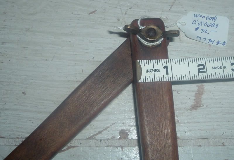
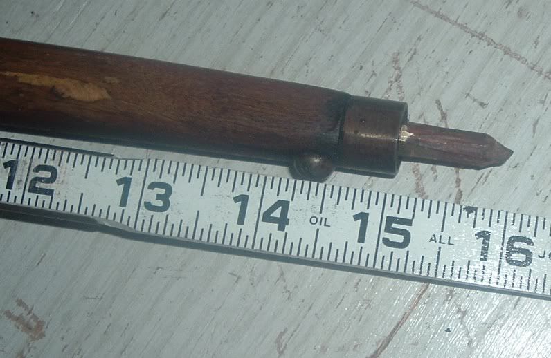
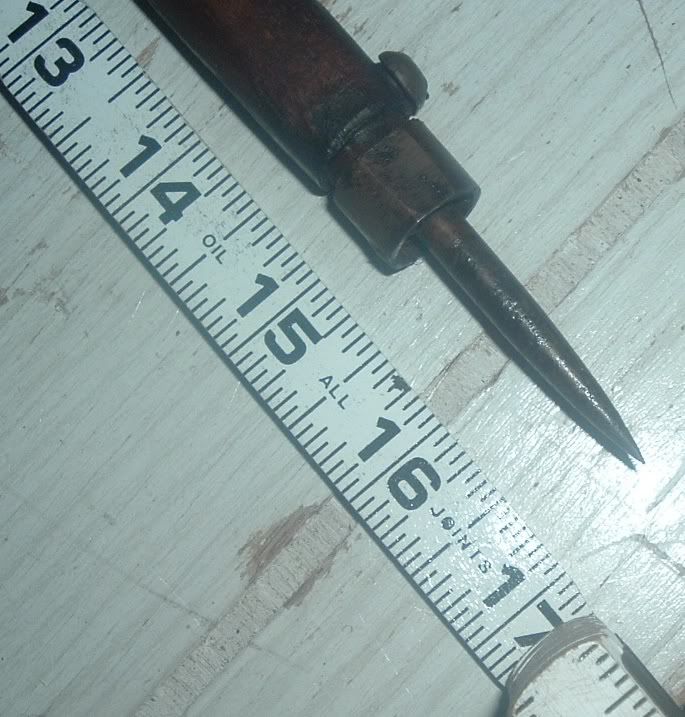
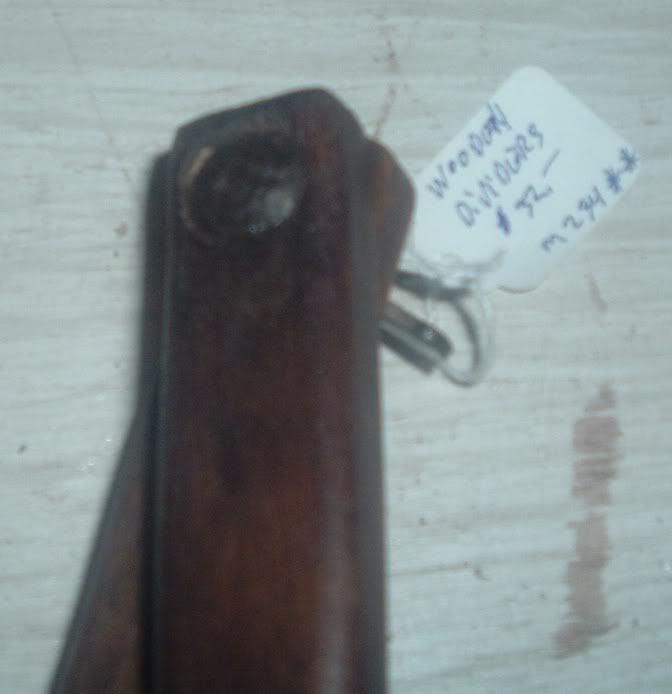
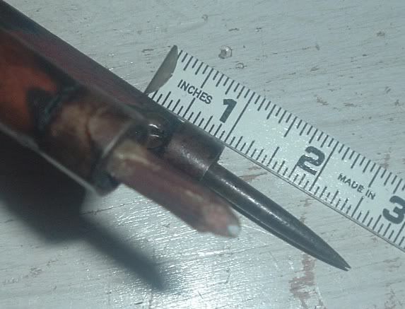
24" dividers are usually available, I currently have one wooden set that has 16" legs, and one metal set that has 21" legs.

I don't have any that are as tall as the pictures show, but I'll watch for them.

In all my years of finding tools, I have not see a set this large. They may have to be custom made, which can be done.
Posted By: D L Bahler

Re: Compass - 02/25/11 11:17 PM

I assumed they would have to be made, that's why I gave some technical information on how they operate. But I did have a slight hope that somebody supplied them.

I suspect 2' is about the maximum size you could manage without having to incorporate the arcs for support. The extra foot of length would make a huge difference too.

I doubt they have been used very much since the 16th century...

2 feet would be a handy size for marking off timbers and laying out joinery, but I am afraid it would be too small for laying out a building plan
Posted By: Jim Rogers

Re: Compass - 02/26/11 02:11 PM

Years ago, at a workshop event before a conference, we watch a pair of French timber framers layout a full size drawing on the floor. They used trammel points to draw large arcs. But that means you have to get down on your knees to do it....
Posted By: D L Bahler

Re: Compass - 02/26/11 08:29 PM

Yes, the whole getting down on the knees thing is unattractive to me. I can see where it would be a lot more pleasant for many years to not have to do that

I am considering making an 'experiment' out of wood with metal points to see how well it works.
Posted By: Dave Shepard

Re: Compass - 02/27/11 01:00 AM

I can't imagine the set in the first drawing are made of iron. They would weigh 50 pounds.
Posted By: D L Bahler

Re: Compass - 02/27/11 03:27 AM

It would make sense. The two retaining arms would be sufficient to ensure the wood doesn't flex or break in use. A nice wooden compass could be made quite attractively as well, with some nice decoration and so forth.

I might just look through my stock and find some nice straight grained wood for this project, some split stock I would think. Of course it would have to be hand tooled! It would just seem wrong to use power tools to make a Medieval compass...

What would be a good wood as far as stiffness and strength. It would need to be able to have holes in it and metal fasteners.

I will draw up some plans and see what I can come up with!
Posted By: Will B

Re: Compass - 03/01/11 10:47 PM

I've seen large wooden dividers at the Maison de L'outil in Troyes (http://www.maison-de-l-outil.com/) and even today compagnons still make their own. We have few modest 2' long sets we made here, with drywall screws filed down for the points.

I think dry beech or hickory would be good woods for this.
Posted By: D L Bahler

Re: Compass - 03/01/11 11:28 PM

I am going to make a 'practice' pair or two out of some 2x4's, just to work out all of the joints and mechanics, and then make some good heavy duty ones out of some nice wood, likely hickory or ash because I have some stock in those, although I could use Osage Orange since I have some split stock in that laying around plenty seasoned. It is super tough stuff, and I wouldn't be worried about it breaking or wearing out!

I was thinking about using pole barn spikes with the heads shaped to fit up against grooves to keep the points from sliding down, with a pin above to keep them from pushing up, and secured to the wooden legs with fence staples. The pin above should be removable so that the points can be removed and changed. This would make them easier to work on if they get deformed, and also allow you to have multiple sets for different uses -sharp points for marking off hard surfaces, rounded points for use on soft ground or grass.

I am undecided whether the retaining arcs should use the friction stop method or be secured at their adjustment with a screw. The friction method would be harder to execute properly

Will, do you have some pictures of your 2' pairs? I would like to see especially how you handled the pivot joint at top.

For this I was thinking of having the wood especially thick near the top, with half laps cut out so that the legs overlap each other and run more or less even with each other. The other possibility is to have a third piece at the top with the legs joined to it independent of each other. This would need some kind of retaining mechanism to ensure that the legs would always be moving together at the same rate, rather than one leg pivoting.

The other possibility is to use a rounded bridle joint at this point, which would be the hardest option to cut out of 1 piece but likely the sturdiest in operation.

the interface between the two pieces is the most complex part, they need to be able to come together at the points, which will either require some complex cutting and reductions at the joint, or making the legs with a double curve to them.

Or I could do like it appears the two compasses pictured are done.

The legs appear to attach independently to a circular handle at the top with pivoting joints of some sort.
Posted By: Gabel

Re: Compass - 03/02/11 01:39 AM

DL,

The challenge (with making any tool I suppose) is not necessarily to make a tool that functions as needed, or even that will look good while it does it, but to make a tool that feels good in the hand.

I don't have any specific input, but I can imagine you want to avoid any design feature that would keep the dividers from being balanced in the hand.

They need to be nice and wieldy. That's what makes a tool a great tool.
Posted By: TIMBEAL

Re: Compass - 03/02/11 01:53 AM

Ash, One piece, necked down at the middle into a thin band, steamed or boiled, and bent into the shape of the dividers. The legs could be nicely shaped and lightened up, light and wieldy. I think you have the pins worked out. The locking mechanism?

Do they need to close completely? I suppose it depends on how thin the middle band is and if the legs need to come completely together.
Posted By: D L Bahler

Re: Compass - 03/02/11 03:48 AM

On the topic of making comfortable tools, that's why I am studying the images from medieval manuscripts and trying to replicate them, rather than reinvent the wheel.

the locking mechanism is in the supporting arcs, you can't trust a lock in the hinge with arms this long
Posted By: Jim Rogers

Re: Compass - 03/02/11 04:40 PM

DL:
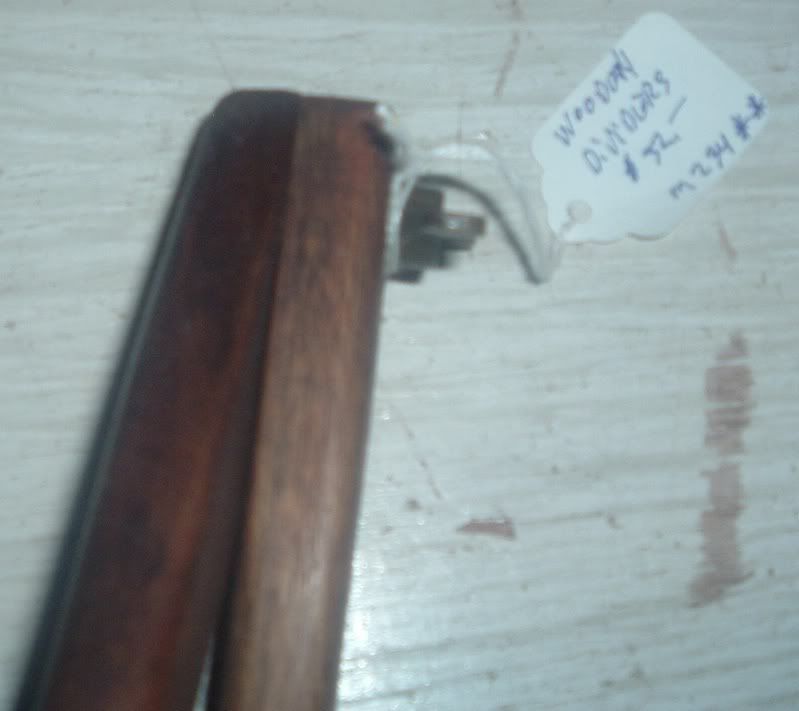
Here are some pictures of the wooden set I have:


If you need any measurements let me know.

Jim Rogers
Posted By: TIMBEAL

Re: Compass - 03/02/11 07:31 PM

Jim, what does the locking mechanism look like?
Posted By: Jim Rogers

Re: Compass - 03/02/11 10:03 PM

Wing nut at the top is all there is....
Posted By: D L Bahler

Re: Compass - 03/02/11 10:51 PM

how well does the wing nut at the top hold 2' arms at a precise adjustment?

Even God uses a compass


I found these interesting as well, an improved version of the drawing compass, the unique design of the legs helps them to hold their adjustment when they are opened widely, and the design of the top portion allows for a sturdy and comfortable one-handed grip. I might make myself a pair of these and see how they work. Recreation based on a carving from an architect's tomb.


Both of these pictures are from this page, http://medievalarchitecturalgeometry.com/Measure%20and%20the%20medieval%20architect.htm, which I would highly recommend to anyone interested in the medieval practice.

see the compass in the bottom right corner.

Note the use of the term compass instead of dividers.
In the middle ages the tool was always called a compass, and it should be called thus whenever it is being used as a drawing tool. The tern dividers came about in the Renaissance when the tool lost its drafting purpose, and was used as a means of dividing (by guess and check) a certain space into equally sized portions. Since we here are not using the tool for dividing, but rather for drawing and measuring, we should call them compasses.
Posted By: Jim Rogers

Re: Compass - 03/03/11 03:57 PM

D.L.
I don't want to start a debate over the correct term/name.
You can call them what you like.
However, it was my understanding from my research that a compass or a "pair of compasses" were when a pencil or pen is attached for drawing on paper or other materials.
When the pencil is removed and the leg is refitted with another spike, the tool is then called a "dividing compass" or a "set of dividers" or a shorten name "dividers"
.
I site as my research this page I found:

http://encyclopedia.thefreedictionary.com/Dividers

And this text:
Dividers

A dividers, also known as a measuring compass, is a mathematical, drafting or cartographic instrument used to aid measurements of the length of irregular lines and of distances on maps or charts. It is commonly used in geometry and in nautical navigation. It is similar in appearance to a drafting compass, the difference being that the compass has a spike on one end and a pencil (or other drawing utensil) on the other which allows the drawing of circles, whereas the dividers has spikes on both ends. Often a compass can be fitted with a spike in place of the drawing utensil and thus converted to dividers.


Which I found by researching the name compass.
And this text from the same dictionary:

Compass (drafting)
In some medieval illustrations, the compass was used as a symbol of God's act of creation

A compass or pair of compasses is a technical drawing instrument that can be used for inscribing circles or arcs. As dividers, they can also be used as a tool to measure distances, in particular on maps. Compasses can be used for mathematics, drafting, navigation, and other purposes.

Compasses are usually made of metal, and consist of two parts connected by a hinge which can be adjusted. Typically one part has a spike at its end, and the other part a pencil, or sometimes a pen. Circles can be made by fastening one leg of the compasses into the paper with the spike, putting the pencil on the paper, and moving the pencil around while keeping the hinge on the same angle. The radius of the circle can be adjusted by changing the angle of the hinge.

Distances can be measured on a map using compasses with two spikes, also called a dividing compass. The hinge is set in such a way that the distance between the spikes on the map represents a certain distance in reality, and by measuring how many times the compasses fit between two points on the map the distance between those points can be calculated.


All of the pictures you have shown, do not show a pencil; most likely as it hadn't been invented, yet, and it may true that the name was changed at the time of the Renaissance, in reality what you are trying to construct, in my opinion, would be a "dividing compass".
Posted By: D L Bahler

Re: Compass - 03/03/11 06:53 PM

No debate intended, just thought a bit of history would be interesting, as the use of the term 'dividers' came about only after the purpose of the tool had changed. To me it seems odd to call the tool 'dividers' if you aren't using them to divide anything. The name 'compass' implies the marking of circles or the swinging of arcs, or earlier simply the use in measurement.

The images do actually show a pencil, just not in the way you might expect it. The architect's compass was pointed with fine silver, which is used as a rubbing drawing point much like lead or graphite. On a properly prepared surface, silver point is erasable.

Today the tool is still most often used for dividing distances into equal parts, rather than as a tool of measurement. As such it is rightly called dividers. But when used solely for geometric drawing and measurement, I submit that the term compass is a superior term. But I admit that may be more because I am somewhat of a medievalist than for any other reason.

I have no issue with people calling their tools what they want, I just thought perhaps I should explain why I am calling it a compass instead of dividers!

I see no need to establish rigid standards of nomenclature, I think it is a good thing for something to have multiple titles. I am no fan of over-standardization. Shakespeare, I have heard, never spelled his name the same way twice...
Posted By: TIMBEAL

Re: Compass - 04/18/11 12:56 PM

Originally Posted By: TIMBEAL
Ash, One piece, necked down at the middle into a thin band, steamed or boiled, and bent into the shape of the dividers. The legs could be nicely shaped and lightened up, light and wieldy. I think you have the pins worked out. The locking mechanism?

Do they need to close completely? I suppose it depends on how thin the middle band is and if the legs need to come completely together.


A while back I made up a compass as I described. I used cedar, and drilled small holes in the feet in which I screwed in broken off screws for the points. To hold it in position I tack screwed a scrap of sticker onto the set to hold it in any desired position. It works very well, the cedar is on the weak side, ash or maple would from a more ridged set.

I have a picture but am having technical difficulties.
Posted By: TIMBEAL

Re: Compass - 05/01/11 12:56 AM

Lets see if I get a photo posted?
Posted By: Jim Rogers

Re: Compass - 05/01/11 12:19 PM

Nope not here yet....
© 2024 Timber Frame Forums