|
|
Joined: Mar 2002
Posts: 1,696
Member
|
|
Member
Joined: Mar 2002
Posts: 1,696 |
Standard layout rule, 2" off layout side 2" wide.....
Whatever you do, have fun doing it!
|
|
|
|
|
Joined: Dec 2007
Posts: 1,882
Member
|
|
Member
Joined: Dec 2007
Posts: 1,882 |
I need a better picture. Is cog the same as tenon in this example? Tim
|
|
|
|
|
Joined: Mar 2002
Posts: 1,199
Member
|
|
Member
Joined: Mar 2002
Posts: 1,199 |
Hi everyone
thanks for the replies--Jim--yes standard layout rule 2" off the layout side-- right--but when you look at the rafter laying beside the one in question notice that the cog seems to be centered,
Timbeal--cog--I suppose does have the same function as a tenon but in a different way, for instance it is not pinned, but it does fit into a mortise cut into the plate, other than that I really don't know what to say.
Cogs do come in different forms, with smaller rafters the cogs will extend right across the whole base of the rafter, in the case of these fairly large rafters the cogs are situated as you see. One thing that struck me though was that for the job that they were doing these cogs seem fairly small, and being shaped on the face would have been harder to cut without an adze.
The thrust fase of the cog no matter where they are used are always are at a right angle to the foot of the base of the rafter, and are a little tricky to fashion. I used an adze as mentioned above predominantly to shape the cogs on the feet of the reconstructed buildings that i was involved with at UCV.
Whenever you are examining existing buildings for reconstruction it is almost impossible to know for sure just what the cog or tenon on a hidden joint truly looks like sometimes you have to make decision based on your experience or if you are lucky you may be able to come across it in research document or historic book written by an author dating to the period that you are working in.
|
|
|
|
|
Joined: Mar 2002
Posts: 1,199
Member
|
|
Member
Joined: Mar 2002
Posts: 1,199 |
Hi everyone:
before I leave this photo of the church frame one of the interesting framing features, that seemed unusual to me at that time, was the ceiling tie beams were on the same plane and in line with the upper plates and the vertical posts
It seemed a wonder to me that there was enough wood left at the point of intersection to make a secure mortise--maybe someone could comment. I did theorize that the tenon from the ceiling tie beams passed through the plates, and the tenon from the post coming up through the plate was short, that would be my own solution.
The only thing that I can say is that they seemed to hold securely for the lifetime of the structure, which was probably over 100 years.
It would be nice to hear an engineer's point of view on this topic and what he would do if asked to reconstruct this building.
I was not able to get up and take a look at that time, and when I went back the frame was demolished and gone.
As I stood there that day trying to visualize the raising that must have taken place, it seemed to me that each whole side of the building must have been raised and then the tie beams inserted in the air from scaffolding. Of course the ends would also have to have been raised first, and then both sides, and then the tie beams, in that order.
I must point out that the whole frame was white oak timbers which would make for strong connections but tough hewing.
I hope you enjoyed this trip with me back to a time when framer's did their own thing------
NH
Last edited by northern hewer; 04/26/08 01:37 AM.
|
|
|
|
|
Joined: Mar 2002
Posts: 1,199
Member
|
|
Member
Joined: Mar 2002
Posts: 1,199 |
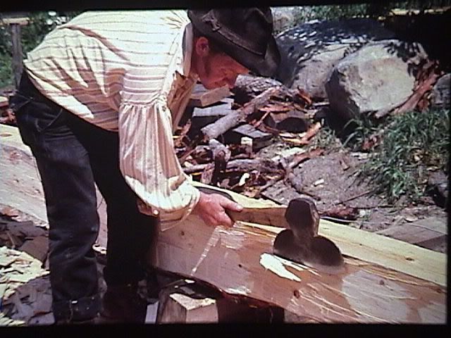 Hi everyone dropping by I think that it is about time to end this thread due mainly to a prompt from a good friend, besides that I truly was considering starting up fresh, so don't go away too far I thoroughly enjoyed having you on board. For those of you that want feel free to continue to wander through these 23 pages of questions and answers, as well as personal photos, I have many more and I promise to bring more to your viewing pleasure as the days roll around. I am ending this thread with a hewing photo of yours truly at UCV working on one of the many timbers used in the reconstruction of the Ross Barn. I will drop by from time to time to answer any questions that you might want answered in regards to any of the posts, if I don't seem to respond just put the finger on me in the new thread so that I realize that there is additional interest to be taken care of here The Northern Hewer Richard
Last edited by northern hewer; 04/27/08 12:33 AM.
|
|
|
|
|
Joined: Mar 2002
Posts: 1,199
Member
|
|
Member
Joined: Mar 2002
Posts: 1,199 |
It seems that many are still visitg this site so I will for the next short while post some additional interesting photos.
I can't seem to get the pics to load so I will try tomorrow night--sorry
NH
|
|
|
|
|
Joined: Mar 2002
Posts: 1,199
Member
|
|
Member
Joined: Mar 2002
Posts: 1,199 |
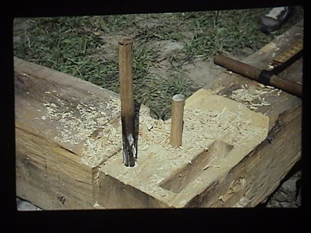 hi everyone: sorry for being so long delivering another photo. This picture shows a corner layout of the mud sill of the Ross Barn just before the raising took place of the upper structure. You will notice the sizing of the timber's seating in reddyness for the corner post You can also see the tallow on the pins, we always kept the wood pins in a pail with tallow, it keeps the pins from drying out, and provides a slippery surface for driving them home with the commander. If you have any questions please feel free to ask Hope you enjoy .
Last edited by northern hewer; 05/12/08 12:14 AM.
|
|
|
|
|
Joined: Mar 2002
Posts: 1,199
Member
|
|
Member
Joined: Mar 2002
Posts: 1,199 |
Hello everyone
Just a further note to this pic before moving on, the seating as you see it here was produced using an adze only and after the ring of sill timbers were slid into position and proper measurements were taken,
On the timber you will also notice the wooden rule that I always kept close by me as I worked. I was taught by my father to always use it along with measuring poles of varying lengths. We used metal tipped poles, these metal tips came out to a square knife like edge on both ends, and varied in lengths from 3' to 16'-- (3', 6', 8', 10' 12', 16' respectively). Metal rules were not used on site, and I will tell you once you became familiar with measuring poles you would not go back to a flexible tape for accurate measurements.
One exceptional use of measuring poles was to square up frameworks both standing and horizontaly while fitting up on the ground. You would measure up the post on the framing line say 6' place a fine nail, and then from the base of the post out 8' on the plate from the same framing line and place another fine nail.
The 10' measuring pole should when everything is square just touch both fine nails. It was at this time that you could check the contact point of the post to the seating on the plate and adjust as necessary, also at this time you could do layout work for the brace holes using the correct measuring pole for that particular building.
What pictures tell!!
I hope that you enjoy
NH
|
|
|
|
|
Joined: Mar 2002
Posts: 965
Member
|
|
Member
Joined: Mar 2002
Posts: 965 |
Hi Richard,
There have now been over 27,000 hits on this topic.
Is that a record for the forum ?
Congratulations
Ken Hume
Looking back to see the way ahead !
|
|
|
|
|
Joined: Jun 2007
Posts: 195
Member
|
|
Member
Joined: Jun 2007
Posts: 195 |
hats off to NH for posting all the awesome info and pics  keep 'em comin' mister
there's a thin line between hobby and mental illness
|
|
|
|
|


