Previous Thread
Next Thread
Print Thread
Rate Thread
Page 4 of 5 1 2 3 4 5
Re: peg placement [Re: Thane O'Dell] #21893 11/28/09 03:20 PM
Joined: Jan 2008
Posts: 918
B
bmike Offline
Member
Offline
Member
B
Joined: Jan 2008
Posts: 918
As far as I understand this has nothing to do with 'tightening' and only to do with the diameter of the bolt (or peg) in question.


Mike Beganyi Design and Consulting, LLC.
www.mikebeganyi.com
Re: peg placement [Re: bmike] #21895 11/28/09 05:36 PM
Joined: Apr 2009
Posts: 235
Thane O'Dell Offline
Member
Offline
Member
Joined: Apr 2009
Posts: 235
Let me get this straight... in the formulas where it says 4D for edge distance, they are not suggesting a 1" peg should be 4" from the edge? When I originally came across these formulas some time ago I thought these engineers were out of their minds. I put the book away and positioned my pegs 1.75" off the edge where I felt it should go in the first place.
If this is true, then I am wondering why they needed to use steel pins in their thought process to position peg holes.

Thane


Life is short so put your heart into something that will last a long time.
Re: peg placement [Re: Thane O'Dell] #21898 11/28/09 11:31 PM
Joined: Mar 2002
Posts: 1,690
J
Jim Rogers Online Confused
Member
Online Confused
Member
J
Joined: Mar 2002
Posts: 1,690
Originally Posted By: Thane O'Dell
... in the formulas where it says 4D for edge distance

First of all, when you say 4D for edge distance are you talking about the peg placement in a tenon or on a post, in the mortise?

This is very important. The peg distances have to be right for both halves of the joint. If you put the peg hole too far into the post it is closer to the end of the tenon. If you put it too far from the end of the tenon then it's too close to the side of the post....

Deciding where to put the peg is something that has to meet code if your frames are going to be reviewed by an engineer or let the engineer decide where they should go.

Sometimes, I've seen at lease one frame this way, the posts were actually made bigger in width and depth to allow the proper peg placement both in side distance and tenon end distance.

Everything has to be taken into consideration in order for it to be strong and safe.

Normally, we were told, at a week long engineering course, that tenon thickness is one quarter the beam width. So an 8x8 has a 2" thick tenon. A 6x6 has a 1 1/2" thick tenon. And then the pegs are usually 1/2 the tenon thickness. So that means a peg going through a 2" thick tenon is a 1" diameter peg. And a peg going through a 1 1/2" thick tenon is 3/4" in diameter. But each joint has to be reviewed and it has to be determined if these "rules of thumb" are ok.

Now that we have somewhat of a standard rules of peg sizing we can then look at the distances needed to make sure the placement is correct. I think that the distance from the end of the tenon to the peg hole, to prevent relish blow out, is very important, as this blow out is "with the grain" and it isn't as strong as the side distance of the peg hole as it is placed on/in the mortise of the post. For the peg hole to fail in the post the peg hole failure is cross grain not with the grain.

To me, common sense would say that the with the grain failure would happen before the cross grain failure. But without searching for the peg report results, I don't have any solid facts to back up that assumption.

When the engineer made that speech at the conference and explained his methods of placement of the pegs using the diameter of the steel bolt and not the diameter of the peg, seemed to make very much sense to me.

I'm not an engineer, nor do a play one... anywhere....
I'm just interested in timber frame engineering.


Whatever you do, have fun doing it!
Re: peg placement [Re: Jim Rogers] #21900 11/29/09 03:11 AM
Joined: Jan 2007
Posts: 217
D
Don P Offline
Member
Offline
Member
D
Joined: Jan 2007
Posts: 217
Quote:
I'm not an engineer, nor do a play one... anywhere....
I'm just interested in timber frame engineering.

Ditto, my hands are too torn up to claim anything more than being a simple carpenter. I do think we build better the more we know, I also hope Ken calls it if we step off the path.

Mike is right, tightening is not part of the consideration here, but the joint shouldn't be sloppy. The design values count on the connector being in shear, a gap will also put some bending in the dowel that was not considered.

Dowel, the NDS term for this type of connection covers nails, screws, lags, bolts and drift pins. Steel "dowels" are used in the NDS since they are the most common wood to wood connection, so what has been extensively tested. The NDS gives minimum specs on the yield strength of the steel in the various diameter dowels, this assures that the dowel is up to the loads listed in the tables. You'll need to check the peg report to keep its stresses within limits. This is the beginnings of the testing that will establish a wood dowel table. I hope to see that in the NDS in another cycle or two. There is actually enough info now to make a preliminary table that would probably be less confusing and thus safer than what we're doing here. But, that's why engineers make the big money.

Some specs;
The NDS minimum edge distance when loaded perp to grain is 4D from the loaded edge, 1.5D from the unloaded edge, that's your mortise. When loaded parallel to grain minimum edge distance is 1.5D , that'll be the minimum edge distance for the tenon. That takes care of edge distances...
End distances;
For the tenon, end distance(relish), loaded in tension, parallel to grain, hardwood, 5D for full design value, for reduced value the minimum can be down to 2.5D. In softwood 7D, min 3.5D. The strength reduction is linear, Cdelta=actual end distance/full design value distance.

Without seeing a table this is probably getting pretty deep for alot of folks so for educational purposes I've scanned a page from the NDS. This is for a bolt in double shear, a tenon in a mortise. The main member here is the tenon. The side members are in tension perp to grain. Look across the top at the red oak column, the middle column under that heading "Zside perp" column is us. Look down the left edge if the tenon is 1-1/2" thick and the mortise sides are >1-1/2" then we are good to go. A 1/2" dowel is good for 960 lbs, 5/8=1310, etc.

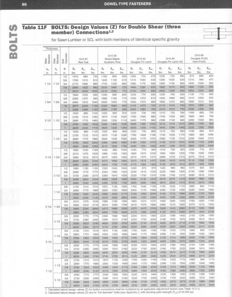
As an example; Assume this is a red oak porch plate and we have a bit under 1000 lbs uplift. We need to adjust the design values for duration of load. Wind is short term so we can multiply the base design value by 1.6. lets check a 1/2" bolt... 960x1.6=1536lbs, OK. A 1/2" bolt would work so our edge distance would be 4x.5"=2" edge distance for the mortise. For the tenon end distance it would be 5x.5"=2.5" end distance. That worked but it was pretty crude.

You can interpolate from the table for a 2" thick tenon but the connections calc would be easier;
http://awc.org/calculators/connections/default.htm
I've set it up for our example but using an 8x8plate and 2" thick post tenon to see if we can get better results;
http://tinyurl.com/yautmr5
I made it with a 3/8" bolt so
4x.375"= 1.5" edge distance
5x.375"=1-7/8" end distance on the tenon

Still need to check the peg for the load but this hopefully gave a quick rundown of how to do the edge and end distances... for a single peg.


Re: peg placement [Re: Don P] #21903 11/29/09 05:31 PM
Joined: Apr 2009
Posts: 235
Thane O'Dell Offline
Member
Offline
Member
Joined: Apr 2009
Posts: 235
Thanks for responding Don.
From the "pegging design" in the "Timber Frame Joinery and Design Workbook" I drew up this sketch based on the min dimensions for an 8x8 timbers using 1.0" pegs.
Because words are open to interpretation I much prefer pictures.
Can you tell me if I understand this correctly.


This is a little different from what I have been doing. For example:

First- The "end distance A" is a little small for my liking. I would like to see this bigger. I fear the peg could cause the post to crack out the end.

Second- (Min edge dist A) My normal has been more like 1 3/4 to 2" inches from the shoulder. 4.0" seems like a lot. In an 8.0" tie beam I would only use two pegs. If it were a 10 or 12" Tie then I would use 3 pegs but the center peg would be staggered out a bit spread the stress line.

Here is the Tie joint in a small frame from this summer.
I am however open to suggestions so as to improve on my "rule of thumb" for designing the strongest joint.
Keep in mind that a picture is worth a thousand words.
Pictures rock... for a right brained thinker like me.


For the record, this frame was approved by our local township engineer.
More than likely he has no clue what he was looking at, scratched his head, and stamped it approved.


Life is short so put your heart into something that will last a long time.
Re: peg placement [Re: Thane O'Dell] #21913 11/30/09 12:37 PM
Joined: Jan 2007
Posts: 217
D
Don P Offline
Member
Offline
Member
D
Joined: Jan 2007
Posts: 217
Hi Thane,
There isn't enough there to go on. Species and load per peg would be the starting point using this method. You seem to be basing the spacing distances in your first pic on the peg diameter? If so that is not my understanding. My gut reaction looking at that joint is that I would scratch my head and call it good.

I have been rereading the translation of the German oak peg studies in the green book, I hope that is the pair of articles you were referring to. Reading those and especially Dick Schmidt's conclusions at the end of each article has helped me see how I think the thought process has been developing on this.

I've been lightly reading the tables in the article, metric makes my head spin. Table 3 in the second article looks like a gold mine. I'll try to convert it and do a little ciphering to see if it agrees with what I think I know.

I've also been reading these papers for more background;
http://www.ewpa.com/Archive/2004/jun/Paper_202.pdf
http://www.ewpa.com/Archive/2008/june/Paper_181.pdf

Re: peg placement [Re: Don P] #21914 12/01/09 01:09 AM
Joined: Apr 2009
Posts: 235
Thane O'Dell Offline
Member
Offline
Member
Joined: Apr 2009
Posts: 235
Quote:
Hi Thane,
There isn't enough there to go on. Species and load per peg would be the starting point using this method. You seem to be basing the spacing distances in your first pic on the peg diameter? If so that is not my understanding. My gut reaction looking at that joint is that I would scratch my head and call it good.


Ok Don, now you have me scratching my head. I just thought that when the data in the design books were specifying spacing by saying: tenon end distance = 7dia., tenon edge distance = 1 1/2 dia. and so on. Is this not spacing pegs based on their diameter? We were after all talking about spacing with regards to steel bolts, were we not? Now you're talking about load per peg, green books and Dick Schmidt's conclusions. I'll have to admit Don, this is too much for me all at once.
It was a mistake for me jumping into this thread the way I did. I will watch this thread from the bench.


Life is short so put your heart into something that will last a long time.
Re: peg placement [Re: Thane O'Dell] #21915 12/01/09 02:09 AM
Joined: May 2007
Posts: 167
T
toivo Offline OP
Member
OP Offline
Member
T
Joined: May 2007
Posts: 167
these questions are on the minds of others too Thane! also, i am getting ready to cut a thru tenon (maybe a tusk...) and your drawing is super helpful in sorting out the possibilities with some precision.

Re: peg placement [Re: toivo] #21917 12/01/09 03:38 AM
Joined: Jan 2007
Posts: 217
D
Don P Offline
Member
Offline
Member
D
Joined: Jan 2007
Posts: 217
Don't run off Thane, I'm treading in deep water too. I was reading late into the night and wrote quickly this morning, it is now again getting late. Just wanted to keep you and those following along posted on what I was reading and thinking. What I'm reading and thinking has no more merit than what you are reading and thinking. We're all, I hope, just collaborating for our common benefit.

After reading your post I flipped through looking for articles on peg design and ended up in Volume 2 (the green book) starting on page 68. Whether I read what you intended or not, I learned a whole lot about what I don't know, so I thank you. Flipping through again I am reading Ben Brungraber's article in Volume1 (the red book). I'm not sure I'm in full agreement but he is one sharp citizen so it bears rereading.

Yes we were talking about spacing pegs based on the diameter of a steel bolt but using a wood peg. If after calculating the load you find that a 1/2" steel bolt would bear the load then the spacing dia is based on 1/2" not 1". In your drawing no load is given so I can't determine what size bolt would bear the load. This is another method of locating the peg from what Brungraber presented.

I've converted table 3 on page 77 of "Timber Frame Joinery and Design, Volume 2" to pounds and inches. It is the top table in this link;
http://windyhilllogworks.com/PegSpacing.htm
The bottom table is my attempt at justifying it with my understanding of the current spacing "rules". I divided the 2 peg allowable load in half to arrive at a single peg load then using the AWC connections calc found the bolt diameter that would carry that load. Using that diameter to calculate edge and end distances according to my understanding of Schmidt. Where the spacings are in black it seemed to agree, where in pink or red the results did not agree. End distances seem to be very conservative using this approach. Kessel and Augustin (the top table) show that a much shorter relish works,and softwood appears stronger than it would seem.

So that's where I'm stuck at the moment, Thane you seem to be conservative according to Schmidt, Schmidt seems conservative according to Kessel and I'm off to reread Shanks and Brungraber and sit on my hands smile

Re: peg placement [Re: Don P] #21922 12/01/09 11:16 AM
Joined: Dec 2007
Posts: 1,882
T
TIMBEAL Offline
Member
Offline
Member
T
Joined: Dec 2007
Posts: 1,882
Can it be simpler than this? Yes and no. All these charts and 4d here and 3d in that direction are tough on a dyslexic brain. Follow traditions is what I try to do. As soon as it reaches into a joint in tension I have to think about it more and with common sense. I will add a wedged half dove tail quickly if there is a question, which can be pecked at as well. in stead of 3 pegs squeezed into an 8" tenon I will do two larger pegs or one, and a half dove tail, wedged. I have even seen no pegs just a wedged half tail but don't go there it was coming apart.

Most joints are in compression so a peg is assisting in assembling and not all that important to holding things together after it is up. 1-1/2" or 2" off the shoulder and centered on the tenon. I don't add two unless the tenon is 8" wide or wider, for the most part. Then you have to look at interference with other pegs coming into the same area and adjust accordingly, something not spoken of in the charts.

I am not bashing the charts or engineers they have to put it forth in such manner to run calculations on all this stuff to satisfy questions. Just offering a different perspective. I haven't reread the red and green books on this of late but should.

Tim


Page 4 of 5 1 2 3 4 5

Moderated by  Jim Rogers, mdfinc 

Newest Members
ScottEllis, ChrisGonzalez, Jackson, Taffswell, CharlieM
5142 Registered Users
Powered by UBB.threads™ PHP Forum Software 7.7.3
(Release build 20190728)
PHP: 5.4.45 Page Time: 0.042s Queries: 15 (0.015s) Memory: 3.2324 MB (Peak: 3.3992 MB) Data Comp: Off Server Time: 2024-06-29 06:12:37 UTC
Valid HTML 5 and Valid CSS