Previous Thread
Next Thread
Print Thread
Rate Thread
Joined: Jan 2008
Posts: 918
B
Member
Member
B Offline
Joined: Jan 2008
Posts: 918
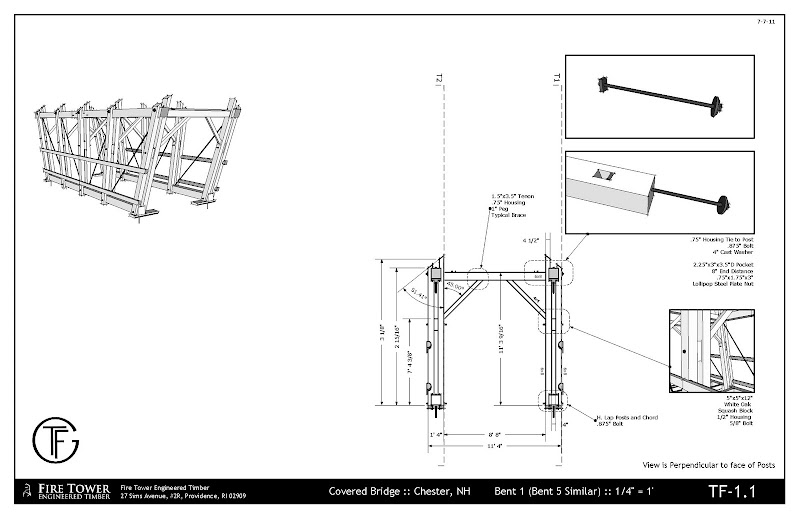
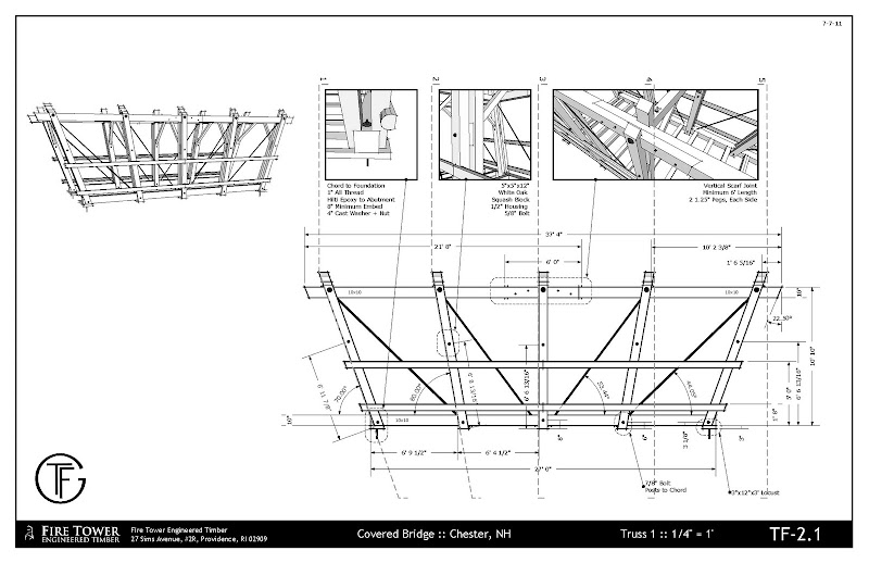
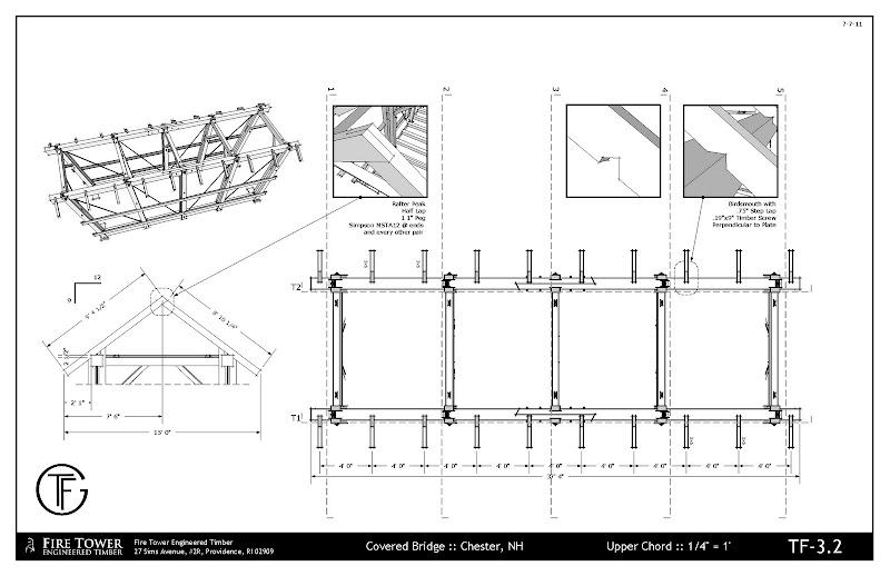
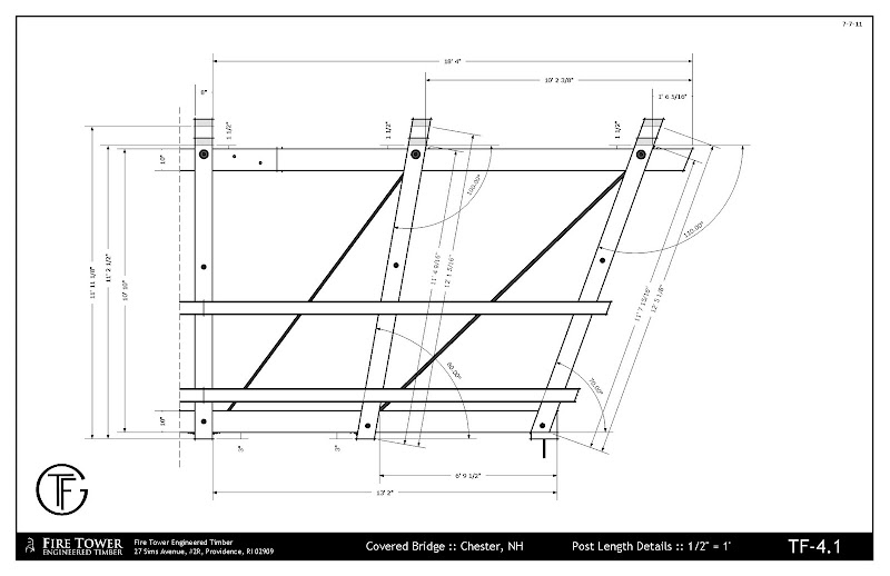
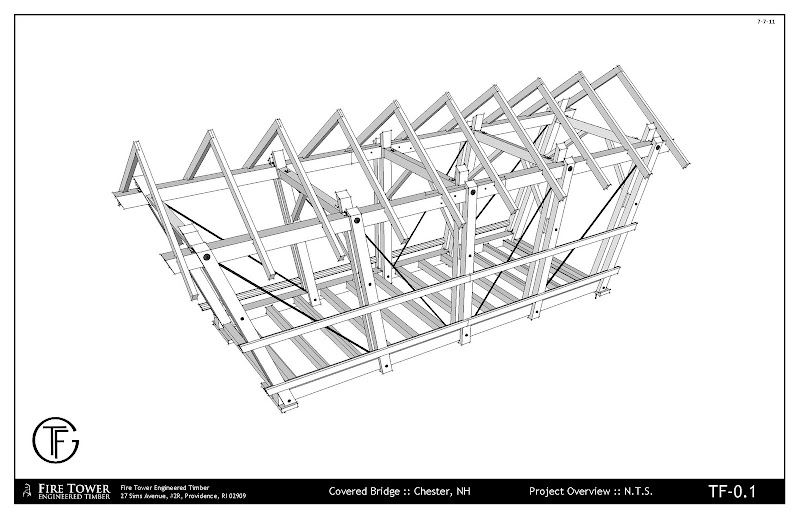
Thought I'd share some images of the shop drawings for the upcoming Chester, NH covered bridge project.

http://tfguild.org/Wason.html


Larger images can be found in the gallery:
http://picasaweb.google.com/mike.beganyi/ShopImages#5626612312526071426


Mike Beganyi Design and Consulting, LLC.
www.mikebeganyi.com
Joined: Feb 1999
Posts: 137
P
Member
Member
P Offline
Joined: Feb 1999
Posts: 137
Beautiful drawings Mike!

Joined: Jan 2008
Posts: 918
B
Member
Member
B Offline
Joined: Jan 2008
Posts: 918
Thanks Paul!


Mike Beganyi Design and Consulting, LLC.
www.mikebeganyi.com
Joined: Nov 2006
Posts: 850
mo Offline
Member
Member
Joined: Nov 2006
Posts: 850
Hey Mike, Those look great. One thing that I like to have on shop drawings is construction lines extended on the paper for setting bevels for lay-out. It doesn't look as nice but is sure does help with the work.

For instance, on the 10 x 10 Top Chord at the ends. You could extend that 22.5 from plumb down the paper. So then during lay-out pull 37' 4 with the long tape, mark, set the angle with bevel off the drawing and the angle is laid out. No computing just transferring. It appears that you have done this with some of the angles. What are the extended construction lines for with the cants?

I hope you don't take my suggestion the wrong way! Your drawings communicate the best as I have seen.


Moderated by  Jim Rogers, mdfinc, Paul Freeman 

Link Copied to Clipboard
Powered by UBB.threads™ PHP Forum Software 8.0.1
(Release build 20251126)
Responsive Width:

PHP: 8.3.33 Page Time: 0.036s Queries: 22 (0.012s) Memory: 2.9800 MB (Peak: 3.5634 MB) Data Comp: Off Server Time: 2026-09-16 14:24:21 UTC
Valid HTML 5 and Valid CSS