Previous Thread
Next Thread
Print Thread
Rate Thread
Page 2 of 4 1 2 3 4
Joined: Dec 2007
Posts: 1,882
T
Member
Member
T Offline
Joined: Dec 2007
Posts: 1,882
Chased back means chased back to the origin, the origin is square rule, the truth is found in that which lies beneath the surface of a timber. Snapped lines bring truth to the timber. In the brace example if one was using rough sawn stock or even planed stock it may have some bow in it, or other defect. If it is not straight the act of drawing 45 degree angles on the ends may result in angles +/- the desired result. So, gaining the end cuts on your brace stock is guaranteed when using a line.

Joined: Jan 2008
Posts: 918
B
Member
Member
B Offline
Joined: Jan 2008
Posts: 918
Yeah, I get the snap line. Certainly makes sense if you have some really wonky stuff. Thought the OP was talkIng about 2 different timbers. I have used that method for twisted posts, odd ball reclaimed, etc. etc.

In general I have gone out of my way to ensure thaty brace stock is straight and square.

And Tim, here in Lake Wobegon all the timbers are square, all the grain runs true, and all clients pay on time.

smile

Last edited by bmike; 06/29/12 11:11 AM.

Mike Beganyi Design and Consulting, LLC.
www.mikebeganyi.com
Joined: Mar 2002
Posts: 1,696
J
Member
Member
J Online: Confused
Joined: Mar 2002
Posts: 1,696
Originally Posted By: bmike
Why would you measure to the dotted line at the inside corner of the housing? Doesn't make sense to me. I always treat the long edge as reference.

Measure to the edge of the ideal timber size. Layout for the 1/2" or ??" housing. Proceed from there. Do the same on the receiving timber. Layout the housing depth from reference. That inside corner will be in the same location.


Ok, well maybe I can explain it more.

You said: "Layout the housing depth from the reference."

In my drawing you'll see that the housing depth was laid out from the reference edge. This is shown by the dimension of 5 1/2". You see in designing a frame I establish some "general frame rules" that all of the joinery has to follow. (Of course there are always exceptions to those rules. But that's another story.)
One of the general frame rules for this frame is that all joints are reduced back to the next 1/2" in size. Seeing that this drawing (which I pulled from some stock drawings) shows that the housing is 1/2" under and that the dimensions says it's 5 1/2" that means that the timber was a 6x6.

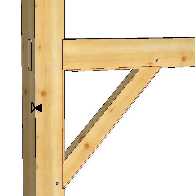
If we look at the larger picture of this brace layout, including the post and tie beam:


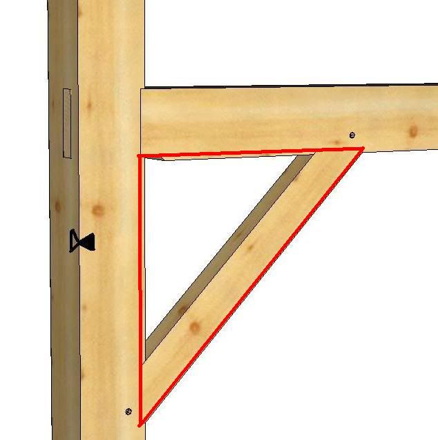
We can see the red triangle that makes up the brace layout.

Here it is as a larger line:


This line is shown here as the brace layout on the tie beam:


The 8" tie beam has be reduced to 7 1/2" at the housing for the brace. The brace layout is 36" shown on the drawing.
So if you draw the diagonal from the "measuring point" on the tie beam to the "measuring point" on the post, it is not along the surface of the brace. It is set back 3/8". The hypotenuse is the third line in the right triangle.

Using the 3/8" layout line on the brace we hopefully will have a brace that end at the surface of the timber of the post and of the tie beam. But that doesn't always happen.

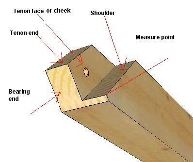
Cutting your brace this way you also increase the bearing area of the end of the brace. This is so that you're just relying on the tenon area but the shoulder area as well:


I'm not completely sure who taught me this layout process, but I believe this is what was done in the past with square rule layout of rough sawn lumber.

I hope this helps all to understand the reason why we use the 3/8" layout line to measure the diagonal for the brace length.

Jim Rogers


Whatever you do, have fun doing it!
Joined: Jan 2008
Posts: 918
B
Member
Member
B Offline
Joined: Jan 2008
Posts: 918
Thanks Jim. Different ways of skinning the beast. I see where you've come to with this setup and how it works for you.

I'm not sure how doing the layout and cutting a brace with your method gets you more bearing. We are both targeting the 1/2" reduction in post and tie size, laying out the post from reference to 7 1/2" on a rough sawn 8x.

If the actual post is 7 3/4" where the brace comes in, in order to get a larger bearing area I would need to note and map a unique brace length and housing depth, then label it and cut it and find it in the pile on raising day. Or change all the braces to a different length and / or housing depth. Am I correct in that? Or are you doing something else to get more bearing?

Regardless, nice to have the graphic examples.


Last edited by bmike; 06/29/12 02:55 PM.

Mike Beganyi Design and Consulting, LLC.
www.mikebeganyi.com
Joined: Mar 2002
Posts: 1,696
J
Member
Member
J Online: Confused
Joined: Mar 2002
Posts: 1,696
Originally Posted By: bmike

If the actual post is 7 3/4" where the brace comes in, in order to get a larger bearing area I would need to note and map a unique brace length and housing depth, then label it and cut it and find it in the pile on raising day. Or change all the braces to a different length and / or housing depth. Am I correct in that? Or are you doing something else to get more bearing?


If the tie beam was undersized as much as that, then there would be less bearing area on the ends of the brace touching the bearing area in the tie beam, for sure.

I don't know if it would mean that we have to go to the extremes of laying out one special brace or housing depth.

Hopefully your timbers are undersized by that much.

If I was buying a 6x8 and it came in as a 5 3/4" x 7 3/4" timber, I'd start looking for another mill. Or at lease let the mill know that these types of undersized beams are not acceptable.

Jim Rogers


Whatever you do, have fun doing it!
Joined: Mar 2002
Posts: 1,696
J
Member
Member
J Online: Confused
Joined: Mar 2002
Posts: 1,696
Originally Posted By: bmike

I'm not sure how doing the layout and cutting a brace with your method gets you more bearing.


Let me show you what I learned at Heartwood school when I took the engineering of timber framing joints class in 2005.

Laying out a brace using the surface of the timber as the hypotenuse of the right triangle will get you a brace that fits into a brace pocket that looks like this:


Instead of this:


In the first drawing above, it's a little hard to see, but you can see the shelf created by the housing. And that the surface of the brace does not meet the surface of the post.

Here is a larger view of the two braces, side by side:


Some may say: "I'm ok with that...." I would say fine with me if you're ok with that.

Now let's say you have 2000 lbs of load coming down that brace into that pocket where there is no bearing area at the housing.

Shown here as the highlighted area in this wire frame drawing:


This highlighted areas is 3" x 2" or 6 square inches.

If you cut the brace with the 3/8" layout line as the hypotenuse of the right triangle you get a bearing area like this:


Of course both timbers have to be nearly the correct size, not 1/4" under as you have suggested.

In the second example the 2" thick tenon is 3" long and there is a 1/2" wide by 4" shoulder bearing on the housing.

In the first example we have 6 square inches, and in the second example we have 8 ((2x3=6)+ (1/2x4=2) square inches.

Ok, so you have two more square inches, what difference would that make?

Well, let's look at the difference in what the bearing areas can support.

In the first example the bearing area is 6 square inches. Using eastern white pine strength values from the NDS we see that compression parallel to the grain (as we are bearing on end grain in the post) is 325 lbs per sq inch for grade 2 post and timbers.
So 325 x 6 = 1950. This is less than the 2000 lbs we got coming down the brace. What will happen? The fibers of the brace will crush until it can bear, if it ever can.

In the second example we have 8 square inches of bearing area.
So 325 x 8 = 2600. We now exceed our load by 600 lbs or about 1/4.
To me it's much stronger and there shouldn't be an fiber crushing.

Next, let's say our post did come in undersized by 1/4".
What does that do to our bearing area?

Now we have ((3x2=6)+(1/4x4=1)=7. Also, 7x325 = 2275 which will still support the 2000 lbs we got coming down the brace.

Does this make sense to you?

Jim Rogers

Last edited by Jim Rogers; 06/29/12 05:08 PM.

Whatever you do, have fun doing it!
Joined: Jan 2008
Posts: 918
B
Member
Member
B Offline
Joined: Jan 2008
Posts: 918
Jim,

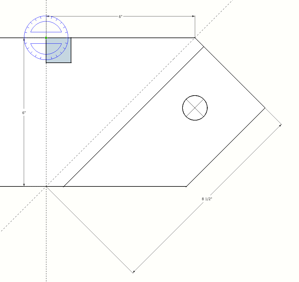
Please see my drawing. I still have a 1/2" (or more) housing going into the post. The dashed line is marked after I set the hypotenuse with my square.


My braces, when cut and installed, look just like yours.
I simply use the long edge of the brace as the reference, mark my start and end, then mark the housing depth along my square and create the shoulder line.


Attachments
Screen Shot 2012-06-29 at 2.19.29 PM.png (23.68 KB, 2187 downloads)

Last edited by bmike; 06/29/12 06:26 PM.

Mike Beganyi Design and Consulting, LLC.
www.mikebeganyi.com
Joined: Mar 2002
Posts: 1,696
J
Member
Member
J Online: Confused
Joined: Mar 2002
Posts: 1,696
A question, when you layout on the post and the tie do you use an even number like: 36", 30", 48"?


Whatever you do, have fun doing it!
Joined: Jan 2008
Posts: 918
B
Member
Member
B Offline
Joined: Jan 2008
Posts: 918
Depends on the situation and the brace size and what kind of material I'm using. It doesn't really matter. The legs are measured on reference faces and located on whatever face they need to be (using a Big All or machinists square for the housing depth, off of reference).

If brace leg is 42", then it is 42" relative to the reference face of the timber it is going into.


So for square rule (and I do not model the reductions in my drawings) a 42" brace is marked 52" down from the top (reference) of an 8x10 tie on the post.

If I am laying out the tie it is 42" from the edge of the diminished housing. (where 2 perfect timbers would meet).

If it is going into a full housing (on a girt, for example) it is still 42" from the theoretical 8x8 timber, and 42" + housing depth from the shoulder of the tie.


Attachments
Screen Shot 2012-06-29 at 2.32.19 PM.png (46.37 KB, 4043 downloads)

Last edited by bmike; 06/29/12 06:44 PM.

Mike Beganyi Design and Consulting, LLC.
www.mikebeganyi.com
Joined: Mar 2002
Posts: 1,696
J
Member
Member
J Online: Confused
Joined: Mar 2002
Posts: 1,696
When you produce your drawings, do you tell the customer the brace length? or do you let them figure it out for themselves?


Whatever you do, have fun doing it!
Page 2 of 4 1 2 3 4

Moderated by  Jim Rogers, mdfinc 

Link Copied to Clipboard
Powered by UBB.threads™ PHP Forum Software 8.0.1
(Release build 20251126)
Responsive Width:

PHP: 8.3.33 Page Time: 0.037s Queries: 37 (0.018s) Memory: 3.0462 MB (Peak: 3.5626 MB) Data Comp: Off Server Time: 2026-09-16 17:21:50 UTC
Valid HTML 5 and Valid CSS