|
 Question on Common Rafter Design
#1448
03/10/05 11:53 AM Question on Common Rafter Design
#1448
03/10/05 11:53 AM
|
Joined: Mar 2005
Posts: 13
dab
 OP
OP
Member
|
|
OP
Member
Joined: Mar 2005
Posts: 13 |
I'm in the process of planning the reconstruction of barn that will be used as a garage. The original barn was a common rafter frame with 12' 8” sidewalls, 30' tie beams connected at the top plate and supported by one post mid span. There were 7 bents. The rafters are 4-6" diameter poles placed 28" on center with a 12/12 pitch. There were rafter ties on every other rafter pair that are about 13' long. There was no ridge board.
I didn't see the original structure before it was disassembled, but it appeared to have a problem with the sidewalls bulging out. The pictures I have are poor, but it looks like steel tie rods were added along the tie beams to hold the walls together.
I want to reconstruct the building as a 30'x40' structure with the same common rafter design (with a 12/12 pitch). I plan to cutoff the original tenons and use timberlinx connectors with the tie beams lower on the posts (9'6"). I'm planning 4 bents, with the same H-design, post mid span.
My main concern and the reason for this posting is that I am concerned about the common rafter design. Should I add a ridge board to keep everything in line with these rough rafters? Should I add a ridge beam to carry some of the roof load?
Thanks
|
|
|
|
Re: Question on Common Rafter Design
#1449
03/11/05 11:15 PM
|
Joined: Mar 2002
Posts: 1,687
Jim Rogers

Member
|
|
Member
Joined: Mar 2002
Posts: 1,687 |
If you lower the tie beam it may effect the outward pressure on the walls called thrust at the plate. This may not be a good thing.
If you added a ridge beam directly supported by the tie beams and posts below it could reduce the outward thrust of the rafters.
A lot depends on your snow load and wind load for your area.
The entire design should be looked at the thought through thoroughly.
Good luck with your project.
Jim Rogers
Whatever you do, have fun doing it!
|
|
|
|
Re: Question on Common Rafter Design
#1450
03/12/05 12:19 AM
|
Joined: Mar 2005
Posts: 13
dab
OP
Member
|
|
OP
Member
Joined: Mar 2005
Posts: 13 |
I was hoping to keep a clear span on the second floor.
Another idea I was playing with was replacing the collar ties with a more complete truss system to resist the thrust created by the roof load. I also considered just lowering the collare ties.
Another factor I need include here is that I will be putting 30,000 pounds of slate on the roof. I will check the and wind load too.
Is it your experience that building inspectors require that lumber be graded?
Thanks,
-Dave
|
|
|
|
Re: Question on Common Rafter Design
#1451
03/12/05 01:35 PM
|
Joined: Mar 2002
Posts: 1,687
Jim Rogers
Member
|
|
Member
Joined: Mar 2002
Posts: 1,687 |
I can only tell you about my personal experiences.
Years ago, I had a customer who wanted to create a new barn from old salvage timbers. These timbers were to be re-cut to smaller sizes to make the timbers for the barn parts.
Their building inspector wanted these salvage timbers grade stamped.
The customer hired a traveling graded to come to my sawmill yard and grade stamp these timbers. He rejected several that he though weren't good enough.
Last year at the TTRAG conference in Southern NH, I met this traveling grader again. He told the group that his lumberman's association will NOT be grading salvage timbers any more.
It was his advice that before you attempt to re-construct a new building from salvage or recycled timbers you check with your building departments, as to whether or not they will allow it or not.
I would suggest you have an informal conversation with your building inspector.
Asking the wrong question will get you a conditioned response. What I mean is if you ask them "Do I need to have my timbers grade stamped?" They most likely will reply: "yes, of course."
But if you tell them what you intend to do and ask: "what will you need from me to allow me to do this?" You may hear that you need your timbers grade stamped, you may not.
My point is don't ask a leading question.
With the fact that you intend to place such a roof load on this recycled structure you should have your plans reviewed by an engineer who is familiar with timber framing, as that is a substantial load on old timbers.
Good luck with your project.
Jim Rogers
Whatever you do, have fun doing it!
|
|
|
|
Re: Question on Common Rafter Design
#1452
03/12/05 05:14 PM
|
Joined: Dec 2002
Posts: 94
jim haslip
Member
|
|
Member
Joined: Dec 2002
Posts: 94 |
DAB,
I'm with Jim on this one. Lowering the Tie Beam will definately add some outward thrust to the wall posts. Could you convert the material to a Principal rafter/common purlin configuration to reduce the outthrust? And with the Slate material going on this roof, I'd definately get an Engineering opinion. Sometimes you just have to spend the money...
Also, the Guild has a book available that deals with the issues discussed here (the red one). If you haven't read it yet, there might be some info in there to help you out. Also, see the downloadable articles on the website here re: Trusses... regards
|
|
|
|
Re: Question on Common Rafter Design
#1453
03/12/05 06:33 PM
|
Joined: Mar 2005
Posts: 13
dab
OP
Member
|
|
OP
Member
Joined: Mar 2005
Posts: 13 |
I don't think moving the tie beams down the posts will increase the outward thust, but it will increase the tension on joint between the tie beam and the post because there is small lever arm between the bottom of the post and the point of force application. That was one of reasons for going with the timberlinx connector, which, according to the companies test data are 5x stronger in tension then a mortise and tennon joint its replacing. 5x sounds like a pretty good safety margin. The other factor going in my favor is the 12/12 roof pitch which directs a good bit of the dead roof load down the post as opposed to the side. Along the same lines, I considered narrowing the building and increasing the pitch beyond 12/12 to take further advantage of this.
For those of you who have built common rafter roofs, do have any suggestions for incorporating wind bracing in the roof without it looking kind of awkward?
Any opinions on the timberlinx connectors. I've also looked at the Simpson Strong Tie Archetectural series connectors but would pre to use a completely hidden connector.
Thanks,
-Dave
|
|
|
|
Re: Question on Common Rafter Design
#1454
03/13/05 05:41 AM
|
Joined: Dec 2002
Posts: 94
jim haslip
Member
|
|
Member
Joined: Dec 2002
Posts: 94 |
On second reading of my last posting, and your subsequent reply, maybe I should not have said that moving the tie-beam down would increase the thrust. The amount of thrust is a given value, as determined by the roof slope, rafter length, roof area, presence of collar ties, etcetera ;however, the effect of the given amount of thrust at the tie beam location will change due to the increased length of post between the Tie Beam connection and the rafter foot. Sorry about that.
|
|
|
|
Re: Question on Common Rafter Design
#1455
03/13/05 02:40 PM
|
Joined: May 2002
Posts: 447
Will Truax
Member
|
|
Member
Joined: May 2002
Posts: 447 |
The ability of the timber-lynx fastener to handle the imparted thrust is a seperate issue from the posts ability to handle the bending moment created by moving the tie down.
Resovling thrust before it reaches the plate will reduce the moment and is in my opinion, always part of good design.
Only an analysis will tell you if the collars are helping with this. If they are near or above the bottom third, it is probable they are not.
The slate should only be considered after someone extremely knowlegdeable looks at your frame and the planned alterations.
|
|
|
|
Re: Question on Common Rafter Design
#1456
03/13/05 05:45 PM
|
Joined: Mar 2005
Posts: 13
dab
OP
Member
|
|
OP
Member
Joined: Mar 2005
Posts: 13 |
Will, You are right that lowering the tie beam has placed a bending moment on the post centered at the tie beam location which did not exist in the original design, but this bending moment is much smaller than moment centered at the base of the post, which is resisted by the tie beam tension. I'm only plannin to lower the tie beam a couple feet.
That said, you guys have got me thinking about this and I'm now leaning toward adding a ridge beam and posts that extend from the middle of each tie beam up to ridge. This would also allow me to add bracing to resist racking of roof.
I will get someone to check my design, too.
I'm trying to do this with the materials I have on hand.
Keep the comments coming, this really helping me. I've also read all of the Ted Benson and Jack Sobon books my library had to offer.
-Dave
|
|
|
|
Re: Question on Common Rafter Design
#1457
03/14/05 01:03 AM
|
Joined: May 2002
Posts: 447
Will Truax
Member
|
|
Member
Joined: May 2002
Posts: 447 |
Dave –
The mere presence of a ridge born by posts does not alone resolve thrust.
This now common framing scheme is known as a “structural ridge” and the key ingredient without which this design will not work, is for some reason I do not understand, almost always not mentioned when this comes up here at AtE.
A Simpson type strap must be present to fasten the rafters either to the ridge or each other, essentially eliminating thrust by putting them in tension and now imparting something more than half of their dead and live load to the ridge and the load path that bears it.
That path, with this design, always going directly to ground.
And “a couple feet” translates into much moment.
Anything greater than say one, requires careful planning, in that the moment increases from every inch thereafter, almost exponentially.
Be your best.
|
|
|
|
Re: Question on Common Rafter Design
#1458
03/14/05 02:24 AM
|
Joined: Mar 2002
Posts: 1,198
northern hewer
Member
|
|
Member
Joined: Mar 2002
Posts: 1,198 |
Hello all:
Great topic, and might I add some comments:
In the older barns the rafter were supported on their centres by a purlin plate. Each rafter was pinned to this plate, and the purlin plates were fastened to each other by a tie beam at each bent. This would eliminate any outward thrust of the rafters to the main plates. These structures stood up well without any signs of stress to the sides of the building until after the early 20th century, at which time due to the advent of hay moving forks and tracks installed into the peaks of most barns, the farmers simply cut off these tie beams to facilitate the movement of hay. It was a very bad move because the wall then began to move outward leading to wall failure.
The analogy of this is in my opinion adding a purlin plate and their tie beams and fastening the rafters well will eliminate in my opinion any stress on the outside wall main plates--check it out!!
NH
|
|
|
|
Re: Question on Common Rafter Design
#1459
03/14/05 11:31 AM
|
Joined: Mar 2005
Posts: 13
dab
OP
Member
|
|
OP
Member
Joined: Mar 2005
Posts: 13 |
I was debating whether to add the purlin plate in the middle of the rafters as NH suggests versus the structural ridge beam supported in the middle and decided that the center ridge beam was a better option for a couple of reasons:
1) The roof load would be transmitted directly to the footer through the center posts that extend from the ridge to the top of the main tie beams that run from side to side then through the posts that support the center of these main tie beams to the floor. The pulin plates would be suppported by the main tie beams midspan between the center posts and the posts on the side. Or, I would need to add additional posts to give the weight a direct path.
2) The ridge solution requires 40 ft less beam since there would be one ridge beam versus two purlin plates.
3) There would be only 2 posts in the space on the second floor versus 4
On the down side:
1) The ridge beam itself might be difficult to shape, and
2) the rafters may sag in the middle without the midspan support or I might need to add additional rafters.
The original barn was 30x76 and I'm reconstructing a 30x40 so I do have quite a bit of extra lumber. Unfortunately I am 4 ft short of having two extra plates to use as purlin plates.
I'll try to post some pictures later today.
-Dave
|
|
|
|
Re: Question on Common Rafter Design
#1460
03/15/05 07:07 AM
|
Joined: Dec 2002
Posts: 94
jim haslip
Member
|
|
Member
Joined: Dec 2002
Posts: 94 |
Dab,
If I've read your last posting correctly, I understand that the "Ridge Post" holding up the Ridge Beam will rest on the Tie Beam. And you are hopeful that the forces (weight) coming from the roof will be carried through the Ridge Post to the Tie Beam and then to the Wall Posts. Am I correct so far? If so, I have a short note for you.
I am currently involved in decking a roof with a similar arrangement. The first ( end wall ) Bent needed a replacement Tie Beam, so we found an aged, matching piece of wood and replaced the Tie Beam prior to raising the Frame. This replacement Tie Beam was crowned up by about 2 1/2 " when it was on the horses being laid out and cut. After raising, the post at mid point of the Tie Beam down to the main deck was short of the deck by about half of that and now that the rafter system and 3/4 of the roof decking is in place, the post has finally touched the floor. So, be careful about trying to get the weight to the outside walls without a post holding up the midpoint of the Tie Beam. What I am experiencing with this frame tells me that the weight will push the Tie Beam straight down if there is no main floor level post system under the Tie Beam.
Alternately, oversize the Tie Beam (a lot... )
And all of this settling has occurred without the weight of the SIP's or Shingles and without the snow or wind load on it.
Best of luck with your project...
|
|
|
|
Re: Question on Common Rafter Design
#1461
03/20/05 02:25 AM
|
Joined: Mar 2002
Posts: 1,198
northern hewer
Member
|
|
Member
Joined: Mar 2002
Posts: 1,198 |
Hi all:
One more comment on this topic:
It seems to me that the timberframers from years gone by would have used the central post arrangement if it was right to do so, but in my travels I have never seen a timberframe constructed with a central post to carry the load of the rafters in the way described above. The average size of the tie beam across a 30 foot wide barn in the early 19th century was 10" by 12", and upwards, and this was with the purlin posts situated a t 1\3 the distance from the exterior walls. This tie beam was usually supported by one vertical post at its centre. I suggest that such a tried and proven timberframe construction should not be varied from, and might I add that one should err on the side of caution when it comes to sizing timbers to do the job and stand up to the continued stresses from wind and snow loads and aging of the structure down the road. One other thought was the installation of bracing from the top of the purlin posts down to the tie beam would assume some of the outward push of the rafters if installed properly, although this placement of the braces is not necessarily historically correct
NH
|
|
|
|
Re: Question on Common Rafter Design
#1462
03/21/05 01:34 PM
|
Joined: Mar 2005
Posts: 13
dab
OP
Member
|
|
OP
Member
Joined: Mar 2005
Posts: 13 |
I had the exact same thought about having rarely seen the center post supporting a ridge beam. Why not? (Although, Ted Benson shows this design in his 1997 book, The Timber-Frame home: design, construction finishing)
One possible explanation for the rarity of this design is that the savings in wood that you would get by having one full length beam (the ridge beam) over two mid-span plates is negated by the need for larger, full length rafters.
Since I already have the rafters in hand, I cannot see any reason why I wouldn’t take advantage of the ability to transfer the roof load directly to ground through the posts. This eliminates the need for over sizing the tie beams since they will be relegated to the principle task of supporting second story floor load.
-Dave
|
|
|
|
Re: Question on Common Rafter Design
#1463
03/21/05 04:42 PM
|
Joined: Dec 2002
Posts: 94
jim haslip
Member
|
|
Member
Joined: Dec 2002
Posts: 94 |
Actually, the roof system decribed above by others was exactly what was in the original frame I'm talking about.(Centre Mid Purlins) We reduced the span of the roof by eliminating an outside bay of the original Bent and converted to a "structural ridge", requiring the centre Main Floor Posts. Many other changes as well, but that's another topic...
|
|
|
|
Re: Question on Common Rafter Design
#1464
03/21/05 09:51 PM
|
Joined: Mar 2002
Posts: 1,687
Jim Rogers
Member
|
|
Member
Joined: Mar 2002
Posts: 1,687 |
Having one center post holding up a ridge beam was a common design in England during certain time periods. These frames are still standing. The center post is called a "Crown post" and it can hold up a structural ridge beam or a beam that runs from gable to gable under the collar beams, thereby holding up the roof and reducing the thrust at the plate. With collars you are also supporting the rafters near the sag point and this would be a good thing considering the load of your roofing materials.
Your design needs to be looked at very carefully as there are many factors in play.
Jim Rogers
Whatever you do, have fun doing it!
|
|
|
|
Re: Question on Common Rafter Design
#1465
03/22/05 02:22 AM
|
Joined: Mar 2002
Posts: 1,198
northern hewer
Member
|
|
Member
Joined: Mar 2002
Posts: 1,198 |
Hi All:
Thanks Jim for that little tip about the central post being used at certain times in England, I wasn't aware of that. I guess we all get carried away by the techniques that were used and practiced right in our own areas. One other thought on the central post theory that may or may not be useful is that the use of 2 purlin plates would leave a good wide open central space area on the second story level. This might help out in the planning stage for future use.
Jim I wonder if you could expand on your statement of "reducing the span of the roof by eliminating an outside bay of the original bent and converted to a structural ridge requiring the central main floor posts" this sort of intrigues me. Do you mean that you narrowed up the building by a certain amount?
NH
|
|
|
|
Re: Question on Common Rafter Design
#1466
03/24/05 05:01 AM
|
Joined: Dec 2002
Posts: 94
jim haslip
Member
|
|
Member
Joined: Dec 2002
Posts: 94 |
Yes, we reduced the width of the building and also reduced the length of the building as well.
|
|
|
|
Re: Question on Common Rafter Design
#1468
04/27/05 10:20 AM
|
Joined: Mar 2005
Posts: 13
dab
OP
Member
|
|
OP
Member
Joined: Mar 2005
Posts: 13 |
Here's how my frame design is shaping up ...  
|
|
|
|
Re: Question on Common Rafter Design
#1469
04/27/05 12:36 PM
|
Joined: Mar 2002
Posts: 1,687
Jim Rogers
Member
|
|
Member
Joined: Mar 2002
Posts: 1,687 |
The first thing I see is that you have several points where there are many timbers jointing the interior posts. This joint is going to be hard to execute.
Which way are your floor joists running? Gable to gable or wall to wall?
Whichever way, lower the supporting member by the height of the joists and run them over the supporting member and you'll eliminate this complex four way joint, as well as others.
Just my thoughts about your design, others may have more input.
Jim Rogers
Whatever you do, have fun doing it!
|
|
|
|
Re: Question on Common Rafter Design
#1470
04/28/05 10:49 AM
|
Joined: Mar 2005
Posts: 13
dab
OP
Member
|
|
OP
Member
Joined: Mar 2005
Posts: 13 |
I see what you mean about the 4-way joint at center posts. There's actually no reason that it needs to be there. I plan on running the floor joists in the gable-to-gable direction and I can offset them from the center post. I wanted to use the half-round logs that were used for the ground floor in the original biulding. As such, they would need to be set into notchs in the tie beams. The picture below shows some of the joists on the right. I also posted a page with pictures of the original barn before dismantling, during dismantling and after dismantling. http://136.142.189.11/Brienza/Barn%20pictures/Page2.html -Dave [img] http://136.142.189.11/Brienza/Barn%20pictures/Barn%20pictures-Pages/Image23.html[/img]
|
|
|
|
Re: Question on Common Rafter Design
#1471
04/28/05 12:27 PM
|
Joined: Mar 2002
Posts: 1,687
Jim Rogers
Member
|
|
Member
Joined: Mar 2002
Posts: 1,687 |
Ok. That's a good plan to offset them so that there isn't a four way intersection at the center posts. Four ways don't leave much post, unless the post is very large.
Another thing I noticed is the beam and brace outside the building. These will have to be flashed or protected somehow from the weather or your inviting rot right into your building.
Also, you have a girt with two braces on the outside walls that mean the wall posts where the tie beam joints. There is a 3 way joint there. How are you going to deal with that?
Jim Rogers
Whatever you do, have fun doing it!
|
|
|
|
Re: Question on Common Rafter Design
#1472
04/30/05 11:37 AM
|
Joined: Mar 2005
Posts: 13
dab
OP
Member
|
|
OP
Member
Joined: Mar 2005
Posts: 13 |
I positioned that girt on the side at the same height as the tie beam to support the ends of the floor boards. I was thinking of using a timberlinx connector that ran from girt to girt right through the post. I'm also considering cutting shoulders into posts if necessary.
-Dave
|
|
|
|
Re: Question on Common Rafter Design
#1473
04/30/05 01:09 PM
|
Joined: Mar 2002
Posts: 1,687
Jim Rogers
Member
|
|
Member
Joined: Mar 2002
Posts: 1,687 |
Dave: I understand that you need something there to support the floor. Here is how I've seen it done: 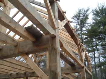 As you can see the floor is the same height as the top of the tie beam. Here he used a floor joist at the outside wall. He cut a slot into the side of the post and slid the joist in from the outside after the frame was raised. This would allow you to support the narrow section of floor out near the wall, and allow you to move your braces up to the level of the plate where the could help support your roof load. Just some ideas I thought I'd share with you. Jim Rogers
Whatever you do, have fun doing it!
|
|
|
|
|