Previous Thread
Next Thread
Print Thread
Rate Thread
Page 3 of 5 1 2 3 4 5
Re: Hand-in-Hand framing [Re: mo] #21988 12/08/09 02:47 PM
Joined: Jan 2008
Posts: 918
B
bmike Offline
Member
Offline
Member
B
Joined: Jan 2008
Posts: 918
Some good information here on the geometry.

This post was slightly modified in order to respect the copy rights of the Author of the book in question. It appears to have been uploaded to SCRIBD without her knowledge or permission.


Last edited by Joel McCarty; 12/09/09 04:23 PM.

Mike Beganyi Design and Consulting, LLC.
www.mikebeganyi.com
Re: Hand-in-Hand framing [Re: OurBarns1] #21990 12/08/09 03:31 PM
Joined: Jan 2007
Posts: 217
D
Don P Offline
Member
Offline
Member
D
Joined: Jan 2007
Posts: 217
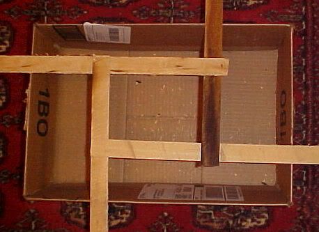
I just did a little figuring, this could be cool, If I'm doing my math right, apparently by dumb luck I'm at the hairy edge of breaking this thing.
Quote:
for the purposes of quick math, if you weigh 200 lbs, each of the 7 "spokes" only need support 28.5 pounds.


So if we carry that thought further... At my weight I point load each rafter with 27 lbs.
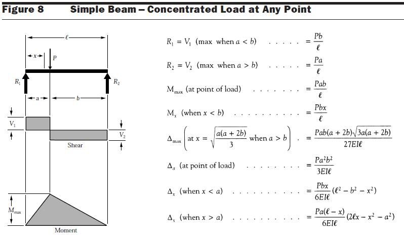
Each rafter in this case is simply supported beam. With a point load at a distance-"a" from one end.


I measured the sticks, they are 19" from the foot to the upper hole, 15" from the foot to the lower hole, so the holes are 4" apart. The sticks are 15/16" square (.9375")

Maximum bending moment is under the joint in the 2 rafters
Mmax=Pab/L
Mmax=(28lbs*4"*15")/19"
Mmax=(1620)/19
Maximum bending moment=85 Ft/lbs

Section modulus required= (Mmax * 12)/Fb This was clear (Select Structural) white pine so NDS allowable Fb is 1250psi.
Sr=(85 Ft/lbs*12"/ft)/1250psi
Sr= (1020 in/lbs)/1250psi
Section modulus required=.816"^3

The formula to determine section modulus of a rectangle is (breadth *(depth*depth))/6
I drilled a 1/8" hole vertically through the rafter at the point of maximum bending moment.
Sm= ((.9375-.125)*(.9375*.9375))/6
Sm= .714/6
Section modulus of my rafters=.119"^3

I would need a section modulus of .816 to be code, I had .119, so I was just a tad overstressed, by code it would need to be about a 1-3/4"x1-3/4" rafter in the model to be safe. But it didn't break... I wondered why. I pulled out the "Wood Handbook" and looked up the Forest Produts Labs test data. Average modulus of rupture for clear, dry, white pine is 8,600 psi
Going back to Sr= Mmax/Fb I plugged in average modulus of rupture for Fb
Sr=1020/8600
Sr=.1186"^3 I was a cookie away and living dangerous smile

There have been more posts since I started ciphering and we got rained out today;
Timbeal, I bent the copper wires straight on the underside this morning, they were just an L shape to keep them from dropping out. Stepped up on it and no difference, held just fine. There is some thrust caused by the deflection of the rafters but not the thrust of an untied pair of rafters. IMO if the rafters were sized correctly for deflection then there would be no thrust. Seems like it would be simple enough to put a tension ring around the outer perimeter though.


Since it hadn't failed yet I had my wife start handing me books.

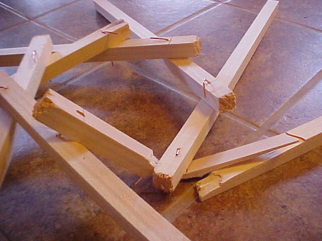
It supported 230 lbs and failed at 235 lbs, the failure was at the hole, the point of maximum bending. Backtracking through the math;
235/7=33.57lbs/rafter
Max moment was 106 ft/lbs
That works out to a MOR of 10,690 psi.
My guess here is that my test apparatus is not frictionless so some of the load was "absorbed" as axial column type loading between the rafter foot and the floor, the deflection thrust. But, off the top of my head that is also within the coefficient of variation in the material, maybe my white pine is better stuff than I thought. I'm not positive of any of this, still just trying to wrap my head around it.

Thanks for the links bmike, more to read.

Last edited by Don P; 12/08/09 03:35 PM.
Re: Hand-in-Hand framing [Re: Don P] #21991 12/08/09 04:10 PM
Joined: Mar 2002
Posts: 344
Joel McCarty Offline
Member
Offline
Member
Joined: Mar 2002
Posts: 344
SOunds like an article for Timber Framing. Are you game?

Re: Hand-in-Hand framing [Re: Don P] #21992 12/08/09 04:21 PM
Joined: Jan 2008
Posts: 918
B
bmike Offline
Member
Offline
Member
B
Joined: Jan 2008
Posts: 918
nice breakdown donp!

i started to step into a model of it... but i'd be lost down that path for days - so i stepped away from the temptation and went back to looking at pictures of bicycles on the internet... (while trying to get some work done...) wink

wondering about the tension ring. i don't think the point load transfers out the length of the rafter - rather it would want to roll the rafter and try to slide down its mate, before pushing straight out - twisting the entire structure perhaps?

obvious in your example that it is not needed in a straight down load, and add some shear planes to it (sheathing, boards, something) and it starts to become a very stout structure.

check out that first link - there are some geometry calcs in there for getting to optimal member sizing vs. number of spokes.


Mike Beganyi Design and Consulting, LLC.
www.mikebeganyi.com
Re: Hand-in-Hand framing [Re: Don P] #21993 12/08/09 05:14 PM
Joined: Apr 2009
Posts: 235
Thane O'Dell Offline
Member
Offline
Member
Joined: Apr 2009
Posts: 235
Don
In your mock up, you are not distributing your weight evenly over all of the beams. Chances are the beam that broke had far more weight on it than the others did. Not quite fair for the poor little stick that broke.

Thane


Life is short so put your heart into something that will last a long time.
Re: Hand-in-Hand framing [Re: Thane O'Dell] #21994 12/08/09 05:22 PM
Joined: Jan 2008
Posts: 918
B
bmike Offline
Member
Offline
Member
B
Joined: Jan 2008
Posts: 918
Originally Posted By: Thane O'Dell
Don
In your mock up, you are not distributing your weight evenly over all of the beams. Chances are the beam that broke had far more weight on it than the others did. Not quite fair for the poor little stick that broke.

Thane


small piece of ply on top would solve that... except then you would be loading the tips of the rafters first. tricky to get it loaded 'evenly'.


Mike Beganyi Design and Consulting, LLC.
www.mikebeganyi.com
Re: Hand-in-Hand framing [Re: bmike] #21997 12/08/09 11:19 PM
Joined: Apr 2009
Posts: 235
Thane O'Dell Offline
Member
Offline
Member
Joined: Apr 2009
Posts: 235
A tall live load which is swaying to and fro transferring more load to one foot or heel. Dead weight evenly distributed using a Styrofoam my work better.
Even still, the little roof stood up well. If that was full size it could hold the "Green Giant".


Life is short so put your heart into something that will last a long time.
Re: Hand-in-Hand framing [Re: Thane O'Dell] #21998 12/09/09 12:21 AM
Joined: Dec 2007
Posts: 1,882
T
TIMBEAL Offline
Member
Offline
Member
T
Joined: Dec 2007
Posts: 1,882
I hear a little gorilla glue will fix that right straight again, and still hold up.

All very interesting.

Tim


Re: Hand-in-Hand framing [Re: bmike] #21999 12/09/09 02:40 AM
Joined: Jan 2007
Posts: 217
D
Don P Offline
Member
Offline
Member
D
Joined: Jan 2007
Posts: 217
Joel, that makes me feel good but I'm certainly out of my league. Surely we can find a more knowledgeable writer on the merits of Christmas cookies smile

Thane, that picture must have been taken during the unbalanced loading portion of our testing. But yes, this is far from scientific or exhaustive. I did try to distribute my load on it better this morning.

I've been doing some reading in the links Mike posted, try this on for size. In a flat reciprocal frame, what Mo introduced this thread with, a grillage floor system, the members have no axial load, they experience only bending. The math I used above should be a fair fit for that situation. This is a model of grillage floor beams atop walls, they could be joined together in one flat plane.

As soon as the members begin to incline they begin to act partially as a column and partially as a horizontal beam. Take the cosine of the rafter angle and multiply it by the load. I think it would yield the bending load. The rest is travelling down the rafter as an axial load.

As an example if the rafters in my model were 20 degrees from horizontal;
Cos(20)= .94, so 6% of the load is axial and 94% of the load is bending the rafter

Now stand them up more
Cos(45)=.71, 29% of the load is carried by the beam as a column and 71% of the load is causing bending.

Getting closer to reality?

Re: Hand-in-Hand framing [Re: Don P] #22001 12/09/09 09:35 AM
Joined: Mar 2002
Posts: 961
K
Ken Hume Offline
Member
Offline
Member
K
Joined: Mar 2002
Posts: 961
Hi Don,

Your reciprocal rafter failure looks like its the result of extreme fibre bending stress followed in turn by a horizontal shear failure.

Regards

Ken Hume


Looking back to see the way ahead !
Page 3 of 5 1 2 3 4 5

Moderated by  Jim Rogers, mdfinc, Paul Freeman 

Newest Members
Bradyhas1, cpgoody, James_Fargeaux, HFT, Wrongthinker
5137 Registered Users
Powered by UBB.threads™ PHP Forum Software 7.7.3
(Release build 20190728)
PHP: 5.4.45 Page Time: 0.032s Queries: 16 (0.009s) Memory: 3.2262 MB (Peak: 3.5815 MB) Data Comp: Off Server Time: 2024-04-20 09:59:00 UTC
Valid HTML 5 and Valid CSS