|
 tying joint design....?
#20576
07/06/09 08:14 PM tying joint design....?
#20576
07/06/09 08:14 PM
|
Joined: Sep 2003
Posts: 120
Bruce Chrustie
 OP
OP
Member
|
|
OP
Member
Joined: Sep 2003
Posts: 120 |
after much frustration with internet explorer I now use Firefox to access the forums....please no followups on that topic but I have missed forum reading! OK I have a first potential paid frame to cut....would be a 15' wide 16' to 20' long frame. King post truss. They want 12" deep top plates and also tie beams but want them to be flush at the top. Jack's historic joinery guide has some suggestions. Dont want to do a gunstock post at all. I was thinking a 5" thick dovetail and am open to feedback or suggestions!   Bruce
Last edited by Bruce Chrustie; 07/06/09 08:16 PM.
|
|
|
|
Re: tying joint design....?
[Re: Bruce Chrustie]
#20580
07/07/09 12:28 PM
|
Joined: Mar 2002
Posts: 1,687
Jim Rogers
Member
|
|
Member
Joined: Mar 2002
Posts: 1,687 |
First of all I think your design will have to be properly reviewed by an engineer to make certain it is safe. My first thoughts are that the dovetail isn't the best for the joint between the tie beam and the plate, as the dovetail will shrink and it may pull out if it does: 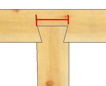 When the dovetail drys out the distance shown above with red will get smaller and the dovetail pocket will not. Therefore it maybe possible for the dovetail to withdraw. And with this being somewhat of a truss the location of the rafter foot to tie beam will have to be correctly done to make it strong. Would it be possible to have three trusses one at each post location and then have purlins run between the rafters? That way you can make each truss a good full length tie beam and connect them with an interrupted plate. This would eliminate two trusses, and the problem of these two trusses joining the plate. The purpose of a plate is to support the rafters. In a truss situation like this the bottom cord, the tie, is more important to supporting the rafters then the plate. This plate is then secondary as it just joins the trusses together. In my opinion then the plate can be interrupted, and not continuous. I'm very interested in others comments about your design, as well as my comments about it. Jim Rogers
Whatever you do, have fun doing it!
|
|
|
|
Re: tying joint design....?
[Re: Jim Rogers]
#20581
07/07/09 01:23 PM
|
Joined: Feb 1999
Posts: 137
Paul Freeman
Member
|
|
Member
Joined: Feb 1999
Posts: 137 |
I agree with Jim that the dovetail will shrink, but I don't believe it will withdraw. It won't have a chance. The low pitch brings the heel of the rafter inboard of the plate on top of the truss chord. So all of the weight of the roof will be carried on the truss chord, at the center from the kingpost and at the heel of the rafter, in both cases creating bending in the chord. However in a properly designed truss the kingpost would be a zero load member, making it redundant. In a true truss the heel of the rafter is connected to the truss chord (well-heeled?:) with a very strong joint capable of resisting the high horizontal outward thrust of the low pitched rafter (hint: steeper pitch, easier job) unfortunately, all that weight on the chord a short distance from its end support creates a very serious shear condition and the chord will shear horizontally at the shoulder on the underside of the chord and the beginning of the dovetail tenon. (Note a second benefit of the steeper pitch is that the point load is brought closer to the post, perhaps even over the post....esp. if gunstocked....
Just because I'm paranoid, doesn't mean it won't fall down, so I prefer to stay away from tension joinery. If I were to build this frame I would turn the truss chords at 1,3, and 5 into beams shouldered onto the posts, sized for the kingpost point load at mid-span, the structural kingposts would support 2 ridges or one continuous ridge, and then you could employ principal rafter - common purlins, or a simple common rafter sytem, being carful in the latter to make the plate sufficient size to carry the rafters at 2 and 4 and plates properly joined to the posts.
Even better, make the kingposts ridge posts to the ground, way stiffer...even if you only put them on the gables the triangulation of rafter, ridge post, and ties would stiffen this frame nicely perpendicular to the ridge.
Horizontal shear on the underside of joists and beams supported in pockets, in my opinion is far too frequently overlooked.
|
|
|
|
Re: tying joint design....?
[Re: Paul Freeman]
#20582
07/07/09 01:44 PM
|
Joined: Sep 2003
Posts: 120
Bruce Chrustie
OP
Member
|
|
OP
Member
Joined: Sep 2003
Posts: 120 |
Actually I am not worried at all about the dovetail coming out. Pine does not shrink that much! Plus there will be minimal horizontal thrust on the plate itself as the rafters will terminate into the tie beam. It is the tie beam itself that would have to absorb that horizontal thrust.
Also not worried about shear on the top plate. remaining wood would be an effective 7x8 and for my area would feel this to be sufficient. I am worried about shear on the tie beam itself at the dovetail though and will go back to them and discuss options I guess. It if funny how people get something in their mind and 'have to have it' like this. Also not so keen on draftspeople drawing up a frame with no knowledge on joinery!
We actually started with a 12:12 pitch roof and had to go down to 6:12 due to some windows on the second floor that would have been partially covered by the 12:12 roof.
|
|
|
|
Re: tying joint design....?
[Re: Bruce Chrustie]
#20583
07/07/09 06:35 PM
|
Joined: Nov 2006
Posts: 850
mo
Member
|
|
Member
Joined: Nov 2006
Posts: 850 |
Hey Bruce, Have you thought about housing the tie beam with a gain (reduction) on the bottom?  That is a 1" housing. 1.5 would probably be better. How do you have your principal rafter meeting the tie? I agree with you about the thrust. From the critical bearing point of your rafter to tie there is significant tension in between, but outside of these points, I would think you only have a downward load. In essence the truss, which negates itself is just inside of the plate and posts. What about two braces from post to tie? One to stablilize the frame, and another with maybe a run equal to where the force from the principal rafter goes through the tie. One brace at a 3' run, and the other at a 1'? You might even be able to have the smaller brace join to the tie at the gain.? Interested in others thoughts as well.
Last edited by mo; 07/07/09 06:49 PM.
|
|
|
|
Re: tying joint design....?
[Re: mo]
#20584
07/08/09 12:53 AM
|
Joined: Sep 2003
Posts: 120
Bruce Chrustie
OP
Member
|
|
OP
Member
Joined: Sep 2003
Posts: 120 |
well considering timeframe I wont be able to brain up on FEA just yet to calculate shear..... so I will likely end up going with something like:  where I will only take out 4" from the bottom of the tie beam and 4" from the top of the plate leaving an 8x8 in each. The tie beam will sit 4" above the plate and that will be the easiest approach I guess to maximize window height under the top plate. also plan to leave a 6" cornice overhanging the top plate since it will be covered in via the exterior wall. Will eliminate any thought of relish tearout or outward thrust on the top plate. Not that there would be much if any. BTW Mo did you use autocad to draw that up? I have yet to figure out how to add nice grain patterns 
|
|
|
|
Re: tying joint design....?
[Re: Bruce Chrustie]
#20585
07/08/09 01:08 AM
|
Joined: Dec 2007
Posts: 1,882
TIMBEAL
Member
|
|
Member
Joined: Dec 2007
Posts: 1,882 |
Nice solution, I think.
I would have flared the post.
Tim
|
|
|
|
Re: tying joint design....?
[Re: TIMBEAL]
#20586
07/08/09 06:33 AM
|
Joined: Mar 2002
Posts: 961
Ken Hume
Member
|
|
Member
Joined: Mar 2002
Posts: 961 |
Hi Bruce,
I agree with Mo that those centre posts are currently a bit "unconnected" and so the addition of bracing across and along the building would help to fix this post in 2 planes, however, when a transverse or longitudinal wind load is applied to the frame the braces would tend to lever up the plate and currently other than gravity nothing else is holding down the tie beam. You might well now realise that the main purpose of the teazle tenon on a Gunstock post is to "close the triangle" and hold the tie down tight onto the wall plate allowing the braces to do their work.
As things stand this whole frame is very vulnerable to collapse and therefore its survival will depend very much on the additional measures that you will be taking to help improve its stability.
Regards
Ken Hume
Looking back to see the way ahead !
|
|
|
|
Re: tying joint design....?
[Re: Ken Hume]
#20587
07/08/09 12:47 PM
|
Joined: Sep 2003
Posts: 120
Bruce Chrustie
OP
Member
|
|
OP
Member
Joined: Sep 2003
Posts: 120 |
Ken,
I am not so sure I agree with the statement that it is vulnerable to collapse from wind loads etc. Actually far from it! In the Sobon guide he does have examples of various forms of lap joinery being held down by a single peg vertically.....no M&T. The gunstock post according to some of his writings was very much a thing of UK structures and seems to have died out a bit in NA.
But yes the potential uplift of the tie beam is easily solved.
Bruce
|
|
|
|
Re: tying joint design....?
[Re: Bruce Chrustie]
#20588
07/08/09 01:59 PM
|
Joined: Jan 2008
Posts: 918
bmike
Member
|
|
Member
Joined: Jan 2008
Posts: 918 |
you could also use *gasp* a metal connector to hold the tie down.
i can't say that i'm a fan of that huge lap you are taking out of the tie. what does the relish outside of the plate do for you, as all the theoretical thrust is taken inside the end of the tie, at the inner corner of the rafter / tie connection (assuming that this works like a truss and we simply don't load the king post to the tie) i also see that hunk just checking and falling off.
and if this is an enclosed and insulated structure running that into the wall will create a thermal bridge and open up (depending on how it is detailed) a path for vapor drive.
without studying the rafter / tie connection i'd be hesitant with just the MT, i'd probably use a girt shoulder and lag it from the top, or a girt shoulder and tenon combination sans lags, although this removes more wood than necessary.
without running numbers a solution might be (assuming an enclosed frame) to house the tie into the plate with a full 1" housing so the tie sits on the post. then run all thread with a timber lock / bed bolt connector from the tie through the plate, about 2-3" down from the top surface. the post gets a tenon into the plate, oriented to the outside with the tenon staying below the steel.
but - all that is dependent on piece size, as I don't think we know the size of the posts nor the rafters and tie, assumptions being 8x stock.
and in terms of wind loads - if you are enclosing this the plywood sheathing and wall system will do more to help with the shear / wind than the timber braces.
Last edited by bmike; 07/08/09 02:00 PM.
|
|
|
|
|

