|
 Re: Designing With the Daisy Wheel
#23912
06/23/10 09:55 PM Re: Designing With the Daisy Wheel
#23912
06/23/10 09:55 PM
|
Joined: May 2010
Posts: 946
D L Bahler
 OP
OP
Member
|
|
OP
Member
Joined: May 2010
Posts: 946 |
The gardener's shelter at Cressing Temple  
|
|
|
|
Re: Designing With the Daisy Wheel
#23913
06/24/10 01:10 AM
|
Joined: Dec 2007
Posts: 1,882
TIMBEAL
Member
|
|
Member
Joined: Dec 2007
Posts: 1,882 |
Ken, I am curious if the common rafters in the 1500's building broke on a purlin or went full length?
Tim
|
|
|
|
Re: Designing With the Daisy Wheel
#23919
06/24/10 03:42 PM
|
Joined: May 2010
Posts: 946
D L Bahler
OP
Member
|
|
OP
Member
Joined: May 2010
Posts: 946 |
Alright, I completed my building layout and am satisfied with its design at last. SO here it is  This picture has on it the layout for the cross section (not a bent layout, because this is going to be a German Fachwerkhaus) the floor plan, roof plan and wall elevation. They are color coded so that it is actually possible to tell them apart! Red = Cross section Blue = side elevation Green = Roof Purple = floor plan. If you study the design, you will notice that Joist and rafter spacing is not the same as post spacing, the posts are spaced further apart. The building will be `14'x24', with a first story with 8' walls and a loft area with 4' walls. The doord will be on the long side of the building. The posts are spaced just shy of 5' and the joists and rafters are spaced at 4' The plan is to make a scale model out of 3/4" pine to test the layout scheme and also decide whether or not this design fits the bill for me. The scale is such that 1/8"=1" so that I can easily use 3/4" stock to represent full-sized timbers
Last edited by D L Bahler; 06/24/10 03:44 PM.
|
|
|
|
Re: Designing With the Daisy Wheel
#23920
06/24/10 04:43 PM
|
Joined: May 2010
Posts: 946
D L Bahler
OP
Member
|
|
OP
Member
Joined: May 2010
Posts: 946 |
Another picture.This is a drawing where I have taken the lines from the diagram and used them to create a drawing of the finished building.  Braces and other secondary timbers use the layout lines as their centers in order to keep them properly centered between the primary members. Joists, posts, and rafters use layout lines to mark edges. All other timbers such as top plates and upper sills (something that is used in this style, but isn't used in American or English style framing) are matched up to the posts and joists. This building has characteristic features of Bernese Swiss architecture, such as very wide overhangs (the roof is double pitched so that the overhangs do not reach too far down) and a half-hipped roof (hence the triangular section at the top of the roof drawing) Every single timber in this building is where it is as a result of the daisy wheel, including the slanting braces. The center lines of the braces are marked by lines that extend to connect points on the daisy wheel somewhere off in the distance. The main reason for this is so that the only tools I need to lay out an entire structure are Dividers and a straightedge, no ruled measurements involved whatsoever!
|
|
|
|
Re: Designing With the Daisy Wheel
#23926
06/25/10 01:00 AM
|
Joined: May 2010
Posts: 946
D L Bahler
OP
Member
|
|
OP
Member
Joined: May 2010
Posts: 946 |
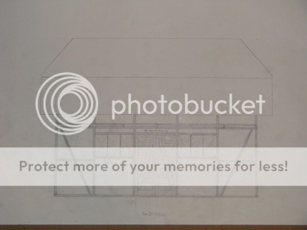 and here at long last is the side view. I left some lines on there as clues to kind of show how I laid out certain features, specifically on the 2 windows. The window is a 1:1.73ish irrational rectangle (ratio of 1:2 short side to diagonal) and is divided into perfect thirds along its length. Try doing THAT with numbers! There will always be something after the decimalTo even establish the window itself required some pretty fancy divider skills. The master radius used to lay out those windows is somewhat bigger than the space between the posts. But triangles and circles will help you find anything! There is a motif above the door, it reads (in German) Im 2010 Jahr (in the year 2010) and is flanked on either side by the Bern Bear. The picture shows the motif on the plastered region above the door, that is an error. It should be carved into the lintel instead. The intent at this point is to cover the roof with red or blue clay roofing tiles (both red and blue clay are available locally, fortunately) in order to keep with the Bernese Swiss style and tradition. This building is my proof of concept for the daisy wheel and general divider layout. at 14'x24' it is larger than any other daisy wheel project I have yet read about. I have got this far without using a ruled measuring device. The next step is the construction of a scale model
|
|
|
|
Re: Designing With the Daisy Wheel
[Re: D L Bahler]
#23927
06/25/10 02:23 AM
|
Joined: Jan 2008
Posts: 918
bmike
Member
|
|
Member
Joined: Jan 2008
Posts: 918 |
To even establish the window itself required some pretty fancy divider skills. The master radius used to lay out those windows is somewhat bigger than the space between the posts. But triangles and circles will help you find anything!
...
at 14'x24' it is larger than any other daisy wheel project I have yet read about. I have got this far without using a ruled measuring device.
With all respect, as I'm interested in how this develops and your process for it - where do you see yourself making changes when function of a space deem the daisy wheel incompatible with the requirements of the program? Or to what extent (as you mention with the windows above) - do you have to gyrate and spin and draw to come up with some geometry that comes from the various rules you've set up for yourself? What is the head height of the windows? Is it relational to the wheel's geometry - or the people or person who will look out of those windows day in and day out? Are they keyed to a view - relating to the outside world - or is this being designed as an object - to simply sit in its environment with its own self contained logic and little relation to the logic of the views / air / sun / wind / etc. around it? And, not to pick - but I find it odd that you describe the building in feet, yet go out of your way to claim that you won't (or haven't) yet used a 'ruled' measuring device. Its cool in a proof of concept sort of way - but is it practical? And why is it 14' x 24'? Wouldn't you describe it with the same language as the wheel...? It seems a disconnect, and I'm not sure how the relationship of 14/24 is derived from the geometry. Is this the footprint you need for the building to do what you want - and then you develop the further geometry from those proportions? Or is 14x24 what happens when you overlap your circles at a particular scale?
|
|
|
|
Re: Designing With the Daisy Wheel
#23928
06/25/10 03:13 AM
|
Joined: May 2010
Posts: 946
D L Bahler
OP
Member
|
|
OP
Member
Joined: May 2010
Posts: 946 |
I described the source and reason of the foot measurements in an earlier post. Basically the reason for that is so that my mind, which is trained in the logic of feet and inches from my childhood, can better envision the finished structure. I set the radius of the circle to 4" so that the wheel would yield imperial measurements, and this ensures that the relative sizes and locations of windows and doors will also be practical. The exclusion of the ruler applies when setting out the design so that I can be assured that geometry rules the day.
In the windows pictured above, the height of the bottom is a little over 4' (the cross beams mark the midpoint of the 8' walls) But they were set up to align with the top of the door more than anything else. However, the window placement on this drawing is not necessarily final placement, I may instead set them so that they sit atop the cross beams (I don't remember the term for these offhand, but it's something in German) Part of the consideration for window placement has to do with the sun. Together with the wide overhangs, I would like for the windows to accept direct sunlight during the winter when the Sun is at a low angle to the horizon, and accept indirect light in the summer when the sun is higher in the sky. That's part of the reason for the somewhat higher placement they have right now.
As far as making changes to fit requirements of real world applications, I deal with this partially simply by having the master radius for the circles set to a measurement of inches. This does yield mostly standard measurements, but it also yields a few irrational numbers as a result of circular geometry.
Why 14x24? Well, because it was set so that the first floor ceiling height would equal 8 feet, this distance is also equal on the diagram to the radius of the circle. The length of the building is equal to 3 radii, or 24 feet. The rectangle that the floor plan is set to is a special daisy wheel rectangle that has a proportional of 1:2 of the length of the short side and the length of the diagonal. Using the Pythagorean Theorem we can find out that the proportional length of the long side would therefore be equal to the square root of 3, which is an irrational number close to 1.732. On the diagram, we know the length only of the long side for certain, which is 24 feet. so 24 feet is equal to the square root of 3 times the length of the short side, so the short side's length (according to my scientific calculator) is an irrational number close to 13.8564, which I have been rounding up to 14 (it is very close to 13 7/8, which would be 13.875, which would be 13' 10 1/2") So that's why! By the way, can you guess I hated math in High school?
We find references here and there to medieval English buildings whose layouts reflect daisy wheel proportions, but also whose measurements match medieval standard units such as the rod. It would seem that the medieval carpenter set his compass to a known measurement. (That's actually where I got the idea) And that makes sense, by doing so you ensure that things are going to come out the size you want them. It also makes it a whole lot easier to figure out how much you need to scale things up from the drawings to make a full sized building. So I guess I wasn't quite right saying I used no ruled measurement, I used 1, and from it all other measurements are derived. So you could say all of my measurements are derived geometrically from 4" I wouldn't go any bigger than 4", and I think 3" or 4" are the best sizes to use, because they both can be used to find useful multiples of feet and fractions of feet. So My quest with a daisy wheel design is to produce a building that will fit with the system. The structure I am working on does that, I believe.
By the way, the reason I don't use a ruler once I've started the design is not because I am morally opposed to rulers or anything like that, it because by doing so I would not come up with something that would transfer as well into the real world, and also doing so would actually be harder than finding things by spinning the compass. Once you start with the system, it doesn't make much sense to try to superimpose some other system over it. For example, would it make sense to design a building starting off with feet and inches, and then at some point switch over to metric? If you start with the imperial system, you've got to stick with it for the whole project or things just won't match up right. It's the same thing, if you start with the daisy wheel then I think you need to stick with it or things just won't match up.
This line of reasoning, however, can run into some flexibility in the area of interior layout. If my building's overall measurements come out as feet, then I feel like it's OK to divide off rooms and such with feet. I will have to experiment some day to see how well you can accomplish that with the daisy wheel though, so far I have yet to see it used or try to use it for any complicated structure.
I plan on creating a conversion scale on my drawing, if nothing else than for kicks and giggles. The point of which would be to get an idea at the size of some of my proportions, and see just how many of my measurements actually come out to be feet and good inches. I suspect most of them will, but we shall see once
|
|
|
|
Re: Designing With the Daisy Wheel
#23929
06/25/10 03:30 AM
|
Joined: Jan 2008
Posts: 918
bmike
Member
|
|
Member
Joined: Jan 2008
Posts: 918 |
DL -
Thanks for the long reply...
While the math and proportions all make sense... I guess I'm more interested in how the geometry meshes with real world program - room sizes, door sizes, bathroom sizes, etc... (and we haven't talked about mashing code requirements into this...)
RE: the windows - have you studied the sun and orientation? Does wheel geometry conveniently make placement so that winter sun can warm the interior and you can be shaded by summer sun? Was the overhang length chosen by the wheel or by sun angle and location on the globe?
I've come at design from a very different side of the problem - orientation / use / program... and then the limits of site / geometry of various materials are used to affect the overall shape. As someone with an art / sculpture background who drifted to architecture - proportion / limits / systems are fascinating to me... hence my questions.
|
|
|
|
Re: Designing With the Daisy Wheel
#23937
06/25/10 10:25 PM
|
Joined: May 2010
Posts: 946
D L Bahler
OP
Member
|
|
OP
Member
Joined: May 2010
Posts: 946 |
Long reply... yeah I tend to do that now and then!
As for windows and doors I would say this: If you are going to use industry standard windows and doors, then there is no need to lay them out with the wheel at all. I laid out my windows because I plan on making my own, and I like the proportions of that particular window. I don't see any difficulty in framing in a standard window or door.
I can't say for certain, but I would guess that you could use the wheel just fine to find room sizes if you wanted. That said, there's no reason at all why you would absolutely have to. The wheel may be the most useful in laying out the overall proportions of a building, after that you could use a measuring tape all you want! Unless you are doing like I am and am making a point to use only medieval techniques and methods throughout. To use the wheel for everything may have little real value beyond novelty or a sense of accomplishment.
The roof overhang on my building was not calculated based on location, It was designed as it was to emulate a specific architectural style.
Keep up the questions, bmike (and others too) these are the things we need to ask!
|
|
|
|
Re: Designing With the Daisy Wheel
#23939
06/26/10 12:37 AM
|
Joined: Dec 2007
Posts: 1,882
TIMBEAL
Member
|
|
Member
Joined: Dec 2007
Posts: 1,882 |
Speaking of tape measures... I use a tape measure on my building. It is based on the daisy wheel but converted to 3/8 = 1' and then to full size. I did not walk the dimensions off with dividers on the full scale building, just on paper. So, it is not true to the wheel as D L's plans are. I am confident it would all walk off, I tested some lengths and they were the same. I used a story pole for other aspects as well, something you would do once walked off lengths are made. 4 large post/braces with a radius cut into them was swung off with a large full size stick with a screw on one end and a notch for the pencil on the other. I find it fun to see how the daisy wheel can answer many questions within a building. I often find building dimensions just picked out of a hat and subject to change or based on the store bought material. A response I tell myself over and over is the wheel made the decision and that is that, it can't be changed. It kind of takes the personal opinion out of the equation. Here is the facebook page with some photos of the building, it was cold back then. It is hard to see, on the post/brace you can see a scaled daisy wheel scratched onto the face. http://www.facebook.com/photo.php?pid=11138693&id=420924555573 Tim
|
|
|
|
|