|
 Designing With the Daisy Wheel
#23838
06/17/10 07:13 PM Designing With the Daisy Wheel
#23838
06/17/10 07:13 PM
|
Joined: May 2010
Posts: 946
D L Bahler
 OP
OP
Member
|
|
OP
Member
Joined: May 2010
Posts: 946 |
OK, so I have often browsed through the old Daisy Wheel Topic and read what is there a few times already. I thought about posting to that topic, but it hasn't been active for quite some time. Beyond that, I have a specific point to make so I decided just to start a new thread.
I want to describe to you all how I use the daisy wheel (well I guess I have used it like twice) to lay out a building. This is the result of a lot of reading and studying, and most importantly experimenting. That last step is the most important, we will never know how valid our ideas are until we try to put them to use. And when we try to use a system like this, certain things only become obvious once we try.
When I first studied the daisy wheel, I looked at these circles and reasoned that the intersection of the various circles was the key to everything. This is of course true, but it is incomplete and very limited. If your building lines rely solely on the intersections of circles, then there are but a few practical structures that can be built.
What is needed are straight lines. I drew a diagram of 7 circles, then took a ruler and connected every point on those circles. What you end up with is an interesting assortment of triangles, rectangles, and useful angles. Of interest is the fact that once all points are connected, the lines form 12 equilateral triangles of equal size within the central circle that all combine to form the "star of David" figure (All 3 angles on an equilateral triangle are, by the way, 60 degrees)
There is also the prevalent rectangle repeated over and over which has a ration of 1:2 between its short side and its diagonal (the long side would be an irrational figure somewhere close to 1.73 times the short side) The daisy wheel also provides a means to divide this rectangles into perfect thirds along its long side -which would be impossible mathematically since the long side is irrational. The figure produced by this was apparently used frequently in medieval windows.
Now when I am laying out a building I can use any intersection as a line of reference, intersections between circles, between lines, and even between a line and a circle. This allows me, with just 7 circles, to create a large number of different building layouts. The best thing is that they all have very excellent and attractive proportions.
Now I like to try to make my designs at least somewhat transferable to standardized measurements -this helps me to get a picture in my mind of just how big a structure will be, and also helps a lot when calculating materials and so on. To do this, I set my dividers to 4 inches, or sometimes 3 inches. Having the radius of your circle equal to a standard imperial measurement will result in a lot of your dimensions easily reflected with feet and inches. I have yet to investigate, but I would feel pretty safe to say it is easier to convert to the imperial system from the daisy wheel than it is to the base 10 metric system, due to the prominence of 12 and of fractals on the daisy wheel itself, and the fact that the imperial system is based around the number twelve, and the inch is broken down into fractals (coincidence? perhaps not...)
I promise you all that I will put up some pictures. I am actually needing to make a new layout for a building I am working on, so I can just take pictures of all of the steps in creating this layout.
Now when I am laying out a building, I lay out every single principle framing member according to my "daisy lines" The most important pieces -the walls, roof line, ties, etc. I lay out using the lines from the daisy wheel itself. But once I have created the basic outline of the structure, I suddenly have a whole new set of lines, angles, and intersections that I can use to lay out the rest of the fame. For example, on one structure I have a double sloped roof, to calculate the slope of the shallower, lower portion I drew a line from where the main pitch intersected one of the daisy wheel's lines to some other point on the chart. Basically if you look hard enough, any basic design will tell you how to lay it out further. I think of it like this: Lay out the basic outline of the building, and then let it lay itself out from there. Just follow its instructions and you will be pleased with the results
Pictures to come, I promise!
|
|
|
|
Re: Designing With the Daisy Wheel
[Re: D L Bahler]
#23842
06/17/10 08:55 PM
|
Joined: May 2010
Posts: 946
D L Bahler
OP
Member
|
|
OP
Member
Joined: May 2010
Posts: 946 |
Here are some pics, with explanations of what's going on. Hopefully this will help clear up any confusion.  If you look really closely, you can just make out the circles scratched onto the paper. I use steel dividers, not a pencil compass, because I don't trust the accuracy of a pencil lead. If I am drawing a scaled down version of a building, then I ought to be sure and be extremely accurate.  I then connect every single circle intersection with every other intersection. This results in a whole bunch of lines. If you study the shapes created very closely, you can learn a lot. I think I could spend all day just studying the wheel at this point. Notice the 12-sided shape, formed by 12 identical triangles, in the center see also the 2 star of David designs. Each comprising of 12 identical equilateral triangles. I could go on and on talking about all of the things I see in the graph if I really wanted to  Look closely and you can see some pencil lines. This is the start of a building layout. Some lines rely on the intersection lines of the graph, other 'secondary' lines rely on the primary building lines. Notice that the Daisy wheel was kind enough to supply me with a method to divide the main rectangle into exact thirds. (You'll just have to take my word for it, the curvature of the camera lens distorts proportions and lines a bit)  Here the layout lines are colored so they stand out. Red lines rely solely on the graph itself, yellow lines rely at least partially on the red lines
|
|
|
|
Re: Designing With the Daisy Wheel
#23843
06/17/10 09:14 PM
|
Joined: May 2010
Posts: 946
D L Bahler
OP
Member
|
|
OP
Member
Joined: May 2010
Posts: 946 |
Rafter Layout:
So one might ask, how do you lay out rafter cuts when you are using the Daisy Wheel? Some have suggested that you might scribe rafter pairs together to get them to match, but I can think of a much easier way. Triangles. If you look at the roof layout in my previous post, you can observe that the roof peak is divided exactly down the center into 2 equal right triangles.
To make the plumb cut at the top of the rafter, one must simply transfer this triangle onto the end of each rafter. To do this, the hypotenuse is aligned along what will be the top edge of the rafter, with the short leg of the triangle oriented toward what would be the center of the structure, or the end of the rafter as it were. The short leg of this triangle supplies you with your exact plumb cut. More accurate than a framing square I would guess. It is important that the vertex where the hypotenuse and the short leg meet be positioned exactly where you want the peak of the roof to come out on the rafter, this way you can be assured that each rafter will come out to the exact right length. Any such angle cut anywhere on the structure can be made in a similar way, all you have to do is transpose the triangles from the daisy wheel onto the timbers. One easy way to do this is to make 3 lengths of some material such as good stout string (that won't stretch too much) each equal to lengths of the triangle, only scaled up a bit (by way of dividers) then orient them until all three points match up. Then you have a perfect triangle.
Now I should also mention how I transfer the lines from the daisy wheel into the reel world. The answer: Dividers
The building shown previously was drawn with a 4" radius circle. If you observe, the height of the walls to the first cross member is equal to radius of the circle. SO if I want the walls to be 8 feet high, then I assume the entire graph to be drawn in a scale of 4" = 8', or expressed rationally 1:24 So that means that I find all real world measurements by setting the dividers to the length of any given building layout line on the graph, and step it off 24 times in a nice straight line. It's very important to have good straight lines or else all of your measurements will end up a little off. If you do this, you can then create a ground layout that allows you to do a french scribe method or some other such method. If you want to do square or mill rule, then you will have to do a little bit of math and measuring to find out how your timbers will actually set up to these lines.
|
|
|
|
Re: Designing With the Daisy Wheel
#23855
06/20/10 04:54 AM
|
Joined: May 2010
Posts: 946
D L Bahler
OP
Member
|
|
OP
Member
Joined: May 2010
Posts: 946 |
It should be noted that All of my building lines are drawn along lines that stretch from one intersection point to another. These points do not have to be matching points or anything like that, just any two points anywhere on the graph. As I said earlier, these points are formed by the intersection of any two marks, whether they be circles, connecting lines, or even the building lines themselves. The points connected to form the building lines often lie well outside of the building's bounds, and sometimes it takes a bit of looking to find a line that does what you want it to do, especially for roof lines. It seems you can really make just about any roof pitch you want. The building in the picture was designed to have a half-hipped roof, hence the horizontal line near the peak.
I really just ought to make a video, or write a book with lots of pictures! I feel like I am doing a lousy job of illustrating how I use the daisy wheel.
I would also be interested in learning how others use this fascinating bit of ancient technology.
And I have a question. Are there any known examples of the daisy wheel's appearance outside of Britain? Is this figure ever found carved onto buildings in France or Central Europe?
|
|
|
|
Re: Designing With the Daisy Wheel
#23856
06/20/10 05:30 AM
|
Joined: May 2010
Posts: 946
D L Bahler
OP
Member
|
|
OP
Member
Joined: May 2010
Posts: 946 |
As for transferring the design into the real world, I.E. making an actual building with the proportions represented in the drawings, there is some degree of difficulty.
The lines on the graph are 1 dimensional. They have only length, and as such they cannot account for the other 2 dimensions of actual wooden timbers. The lines merely mark centers and intersections, they do not really tell where a timber 'is'. We run into the greatest difficulty at joints where timbers do not join at the same height, for example in an English tying joint, or certain rafter joints. In such instances, you have to come up with a way to account for this variance.
To convert your building from the 1 dimensional lines of the graph to 3 dimensional reality, I can think of 2 methods. The most obvious method is the French Scribe method. Here we simply take of design and enlarge it, creating a full-scale version of it right on the ground, using strings stretched across or some such method to represent the lines off of the design. Then we are free to align our timbers with these building lines and scribe our joints onto each other. Observe, however, that these lines usually represent outer edges and not necessarily center lines running down the middle of timbers. For example, the lines for the walls should be taken as representing the outside of the posts, and a horizontal line should represent the bottom of ties and joists. The main reason to do this as I see it is so that, assuming you set your dividers so that standard measurements would result in the final building, predetermined distances such as building width and interior ceiling height will still retain their imperial measurements (or metric, if you absolutely must) For example, on my building I set the dividers at 4" so that I could have a ceiling height of 8 feet, and a total length of 24 feet. If I do the layout as described then My building's length should measure exactly 24 feet from end to end, measuring from outside corner to outside corner, and my wall height should measure exactly 8 feet from top of floor joist to bottom of ceiling joist. Note that should you decide that you would rather have your wall lines mark the inside edge of your posts, then you are going to run into a lot of trouble once you start running your rafters.
Another reason to do it this way is that it allows you to use irregularly sized timbers. In other words, all of my timbers do not have to be exactly 6 inches wide (I use rectangular, rather than square, timbers, so they might be as narrow as 4 inches at times, with a depth of 9 inches or more)
Now I was just thinking about 2 story buildings. In this case you may want to make an exception to the rule of layout lines marking an edge rather than a center. If you don't line up the first floor joists with the line marking the center, then the second story is going to be several inches shorter than the first. If you do, then both stories are going to be a little bit shorter than the ideal size. So It's a matter of choice, would you rather have A nine foot first floor and an 8 foot second floor (which would result if you laid out your building to have 9 foot ceilings, aligned the bottom of you joists to the line, and use 12 inch joists) or 2 8'6" stories (same layout for wall height, only the 12" joists are aligned with the line marking their center)
Really the only rules that I would set in stone are that: Building lines mark the OUTSIDE of posts, and roof lines mark the BOTTOM of rafters. It might be beneficial to actually have one or two lines here and there be a center line, with others marking edges.
There is another way to do it that doesn't require creating a full scale layout, so that you can cut all of your joinery in a smaller area like a cluttered shop or a crowded city lot. I thought of this one day while taking a shower -I doubt I am the originator of this idea, it's probably a way that someone used hundreds of years ago, but I had never heard of it that I remember.
Basically the idea is this: Take a given framing member, let's say it's a post. This post s stepped off for length, the length being set to the full distance between the two lines it is bounded by on the drawing. Note that the space between the bounding lines is not the same as the actual length of the post. Add a little extra yet for good measure.
Then any other timbers that join this post should be matched up and scribed and so forth. Let's say there is a plate running along the top, and on top of that is a tie beam. All three of these timbers need to be scribed together right now, aligning the bottom of the tie with the mark on the post for total ceiling height. Here you will glad you left some extra on the post, because it may tenon into the tie just a little bit, in which case the post would actually be longer than the distance between bounding lines. It will also need to tenon into the sill below, in which case even more additional length is added, assuming that the top of the sill is aligned to the bottom bounding line of the structure (to maintain interior wall height)
To do it this way, you'd have to have a lot more faith in your ability to step thing off correctly, because you don't have a nice big layout to constantly reassure you that everything is right.
|
|
|
|
Re: Designing With the Daisy Wheel
#23857
06/20/10 08:17 AM
|
Joined: Mar 2002
Posts: 961
Ken Hume
Member
|
|
Member
Joined: Mar 2002
Posts: 961 |
Hi D.L
This forum is an ideal place to pose questions for the timber framing community to try to help you by providing answers or opinions that might help fill gaps in your own knowledge base and of course that of others.
It is becoming obvious that you are approaching a point where you really should consider writing articles for publication that could be better supported with photos, illustrations and of course appropriate references.
Some of the aspects that you raise above are in the process of being researched by others (Laurie Smith) with some articles having already been published in "Timber Framing", "Mortice and Tenon" and "Vernacular Architecture" journals.
I would like to encourage you to reach a wider sudience where the content of your topic could be subjected to peer review in order to help establish reliable outcomes.
Your message is important and is in danger of being lost if simply confined to this forum.
Regards
Ken Hume
Looking back to see the way ahead !
|
|
|
|
Re: Designing With the Daisy Wheel
#23858
06/20/10 11:13 AM
|
Joined: Dec 2007
Posts: 1,882
TIMBEAL
Member
|
|
Member
Joined: Dec 2007
Posts: 1,882 |
And, by all means your contribution here on the forum is welcome.
The daisy wheel, in my opinion, is a underused tool. Somewhere here on the forum a short term poster posted an older barn for sale, it used curved brace stock and a close bent system, both appearing to fit the same circle. When I have more time I will look for it or someone else may link to it.
I know of one small building that is daisy wheel constructed, I think it was moved out west. Built by a group directed by Laurie Smith just last fall. I added onto my existing house this winter using a two circle lay out. I have not compiled all the "how I did it" in a why clear enough way for the forum. I did wander a bit and used a healthy bit if fudge in getting from paper to reality. I should at least post a photo of the lay out on paper.
I didn't go all out with connecting as many points as you suggest, I think I went in the opposite direction and used just a minimum of points. There was already some dictated points, as I had previously constructed the foundation, so I was working with in a set of givens. Excuse my vagueness I will see if I can put up a picture, I have been meaning too.
Tim
|
|
|
|
Re: Designing With the Daisy Wheel
#23860
06/20/10 04:21 PM
|
Joined: Mar 2002
Posts: 344
Joel McCarty
Member
|
|
Member
Joined: Mar 2002
Posts: 344 |
Hear hear! Contact me for advice and encouragement regarding publication of your work.
|
|
|
|
Re: Designing With the Daisy Wheel
#23861
06/21/10 02:29 AM
|
Joined: May 2010
Posts: 946
D L Bahler
OP
Member
|
|
OP
Member
Joined: May 2010
Posts: 946 |
Ken,
I wanted to post this here for 2 reasons, 1: to show my methods to others so that they could learn and hopefully improve upon them, and 2: to set up my methods for critical review -to let others pick through and see where I may be wrong or doing things the hard way when there is a better way.
What I have presented here is the result of a lot of research, reading what little material is available, or at least that I could find, on the subject. Although I am certainly open to the idea of publishing these things for the benefit and review of a wider audience.
Tim, the connection of points has been a major question for me. It is hard to decide how far to go on connecting things. Should you only connect the points within and along the central circle? This limits you, and does not allow you to cut the circle into quarters for example. Should you connect all opposing points, i.e. those points that are reflected across the center of the diagram? My opinion is that any way you come up with will work, but the Daisy Wheel will reveal a whole lot more to you (in my opinion) when you connect everything. When I draw the last line, everything falls into place and some interesting geometric figures pop out at me. I believe it is also important to note that the same ratios are to be found in the complex diagram as can be found in its simplest form, just in greater number. The biggest benefit I see is that when you do connect everything, the building truly does begin to lay itself out in front of you. After you draw the first couple of lines, establishing the most basic outline of a structure, everything else becomes incredibly obvious. It's really quite remarkable.
I also try to work with a set of givens whenever I can, because that makes real world work so much easier. The daisy wheel does seem to let you force things on it if you must, although it will be a little more difficult.
Joel- certainly! If you think that is the way to go.
Now I asked this question once before, but no one seems to have answered it.
Are there any known examples of the Daisy Wheel being inscribed on timbers or masonry anywhere in continental Europe? IS there evidence that this was a universal Medieval technology, or was it confined to England? Have any medieval German or French or other buildings been shown to reflect daisy wheel dimensions, as Mr. Smith has shown many English buildings to do?
|
|
|
|
Re: Designing With the Daisy Wheel
#23862
06/21/10 07:03 AM
|
Joined: Mar 2002
Posts: 961
Ken Hume
Member
|
|
Member
Joined: Mar 2002
Posts: 961 |
HI DL,
This symbol is widespread across Europe and elsewhere.
Regards
Ken Hume
Looking back to see the way ahead !
|
|
|
|
Re: Designing With the Daisy Wheel
#23863
06/21/10 03:13 PM
|
Joined: Nov 2005
Posts: 305
timberwrestler
Member
|
|
Member
Joined: Nov 2005
Posts: 305 |
DL, I don't quite follow your reasoning for using your daisy wheel lines as the bottom of rafters and tie beams. The Laurie Smith Dutch project from last fall went down to Texas. I think he was going to set it up at a school. Here's the basis of the geometry and the final frame. 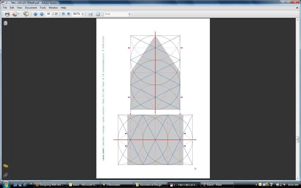 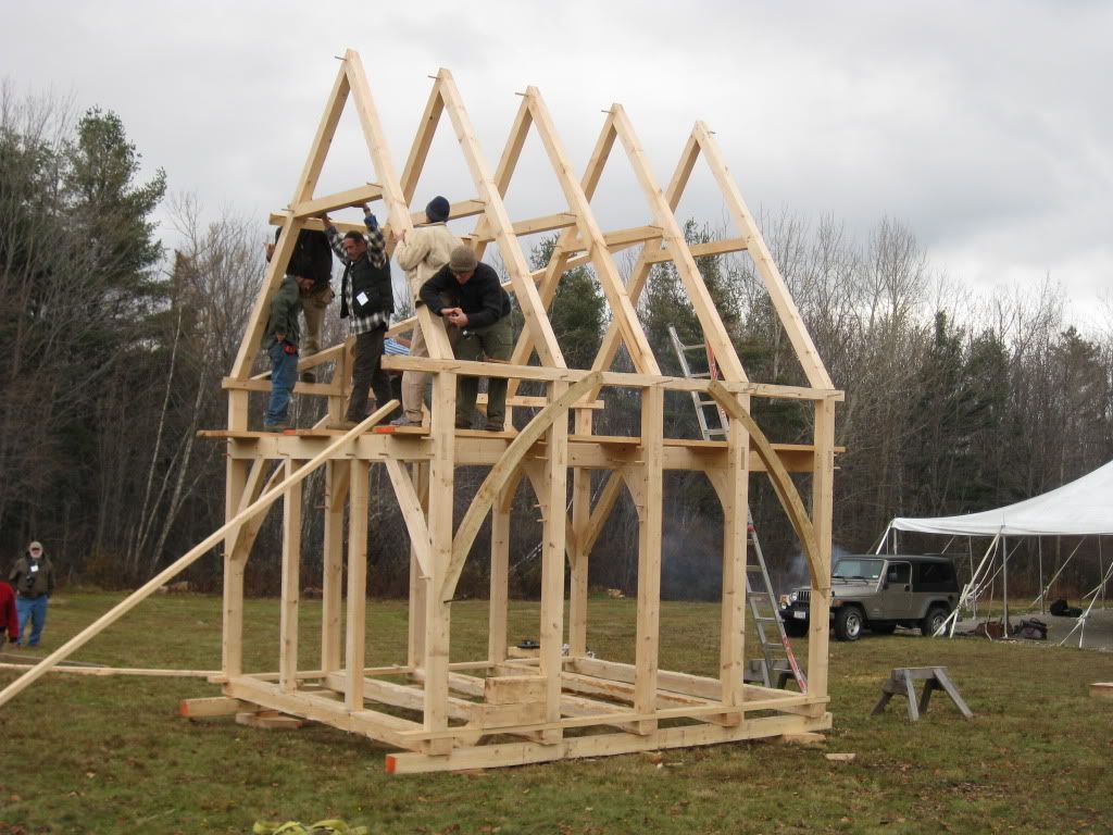 We also used several tricks of Laurie's to lay things out full scale. First of all, we would often set up the dividers to twice or 3 times the base divider distance, so that you would step off 8 times or 12 times instead of 24 times. We also used rods with holes drilled in them at the appropriate distance, and a sharpened 20D spike poking through the hole. We set the rods up as equilateral triangles with the trammel points running through, and laid out our floor plan that way. I don't think I have a picture. You can also just get your tape measure out... I think the Guild has a few copies of the little book documenting the garden shed built by Laurie a few years ago. I was blown away by his finding of a geometry in the crazy asymmetric vaulting of Lincoln Cathedral. There are rumors circulating that he may be back this fall.
|
|
|
|
Re: Designing With the Daisy Wheel
#23871
06/21/10 07:12 PM
|
Joined: Mar 2002
Posts: 344
Joel McCarty
Member
|
|
Member
Joined: Mar 2002
Posts: 344 |
We DO have a few copies of Laurie's book in the basement.
Find it on the tfg webstore.
|
|
|
|
Re: Designing With the Daisy Wheel
#23873
06/21/10 10:07 PM
|
Joined: May 2010
Posts: 946
D L Bahler
OP
Member
|
|
OP
Member
Joined: May 2010
Posts: 946 |
The reason I chose to have the lines mark the bottoms of rafters (and it is my choice, it's the way I do it, not the way it has to be done) is because it simplifies things for me when it comes to actually laying out the joint, assuming that other lines marked edges and not centers. If you choose to use your horizontal lines as center lines then your rafter lines have to be used as center lines too. I guess if you get right down to it, if any one of your primary lines mark a center then all have to mark a center, and if any mark an edge then all have to mark an edge, in order to keep joinery consistent and matching.
I thought I'd present that idea, assuming that it was normal to use the lines as center marks rather than my idea of using them for edges. It was presented as another possibility.
I think of it like this: When you are laying out studs for a stick framed building, do you make your marks on your plates for the centers of the studs? If so, you do it much different than anything I have ever learned. In stick framing, you mark the edges because it makes layout easier, and it also makes measurements conform to standard units. That's the exact same reason why I thought to do that with my daisy layout lines.
You may see logic in doing it otherwise, and I have not problem with that at all!
The rods to set up triangles is a great idea, thanks for that! I have found the string setup to be quite unsatisfactory because string tends to stretch, throwing off your accuracy.
I should talk a little bit about triangles. Triangles are my way of transferring things from the circles of the daisy wheel to the rectangles and lines of a building. I mentioned earlier that triangles can be used to mark rafter plumb cuts (and horizontal cuts) They can also be used to establish perfect right angles -I use the 3:4:5 side ration right triangle. If you make a triangle with a side relationship of 3 units for one side, 4 units for another, and 5 units for the last, then you will always have a perfect right triangle, which will allow you to lay out perfect right angles.
So with my fondness for triangles, I am very excited to have learned this trick as to how to use them! Thanks a whole lot!
setting the dividers to a multiple of the distance is quite handy, and I think you will actually be slightly more accurate that way (my opinion)
One thing I would recommend, If you are laying out a full scale floor plan don't use your dividers to step off the distance -use rods (which I am pretty sure is authentically medieval)You make a rod with pointed ends, set to a distance determined by the calipers (2 or 3 or 4 times the size of a line on my 1:24 scale drawing, for example) Then you just turn the rod end over end along a string that has been stretched out to make sure you're running straight. This way you can easily lay out a building on grass or dirt ground, or even a somewhat uneven surface.
For e personally I find that dividers are great for stepping off timbers. They work best when their sharpened steel points can set into a surface just a little bit, but not cut in (like in dirt) I don't like using them on concrete because it's hard on their ends.
Also... I REFUSE to get my tape measure out! Except for maybe here and there to test theories and relationships (ok, so a I use a tape measure to rough cut logs to length before they are squared, and I use an inch ruler and a bubble level to mark the size of timbers to be hewn)
and Ken, thanks for the info about the spread of the daisy wheel
Last edited by D L Bahler; 06/21/10 10:16 PM.
|
|
|
|
Re: Designing With the Daisy Wheel
#23874
06/21/10 10:26 PM
|
Joined: May 2010
Posts: 946
D L Bahler
OP
Member
|
|
OP
Member
Joined: May 2010
Posts: 946 |
Actually I should revise my statement about what lines mark. Mostly because I oversimplified things. Really What the lines mark depends on a number of factors, but most importantly the type of joinery used.
If your tie beams join at the same level as the plate, then perhaps your rafter lines need to mark an edge. If they join above then perhaps the lines need to mark a rafter's center. If below, then it's not really important so long as you are consistent. Or it could be a matter of what you want most to conform to the line. Personally I choose ties and joists because I find interior wall height to be more important. Someone else may choose to set rafters as their standard (which is maybe better in a barn or shed or some such) I will draw up some diagrams to illustrate what I mean.
|
|
|
|
Re: Designing With the Daisy Wheel
[Re: D L Bahler]
#23875
06/21/10 11:33 PM
|
Joined: May 2010
Posts: 946
D L Bahler
OP
Member
|
|
OP
Member
Joined: May 2010
Posts: 946 |
 Here is the picture I promised. This shows an English tying joint style of post/plate/tie connection. Here you can see the plate is bisected by the horizontal line, but that is not always necessarily the case, that's why I choose to define it as the bottom of the tie is marked by the line. I hope this clears thing's up a bit This system works just fine whether you are joining truss rafters into the tie beams (with no overhang) or running rafters across the plate for an overhang. In case it is not immediately obvious, the end of the tie beam can be cut off at an angle to accommodate narrower rafters
|
|
|
|
Re: Designing With the Daisy Wheel
#23876
06/21/10 11:40 PM
|
Joined: Dec 2007
Posts: 1,882
TIMBEAL
Member
|
|
Member
Joined: Dec 2007
Posts: 1,882 |
I tried linking google maps but with no success. If you zoom in on the Washington Monument you will find a 2 circle layout similar to Brads posting of the little frame cut in the workshop. An example of geometry used here in the U.S. And isn't that something.... the monument coming right out of the vesica.
In my example the two circles just kiss, they do not over lap.
Tim
|
|
|
|
Re: Designing With the Daisy Wheel
#23880
06/22/10 03:05 AM
|
Joined: May 2010
Posts: 946
D L Bahler
OP
Member
|
|
OP
Member
Joined: May 2010
Posts: 946 |
There is another way to view these layout lines as well, as I sit here pondering their meaning...
These lines can also be used as lines of balance, and as lines of balance they can also be stated as lines of strength. They are lines of weakness in a sense, and weakness can be harnessed to yield strength.
They are lines of balance not of each individual timber, but of the joint and of the building as a whole. The building is not any one of it's parts, nor is it merely the sum of it's parts. If we stacked an assortment of timbers on a pile, they would not create a strong building. Each one sits there unyielding, with no interaction with the other timbers all around it. Even if we stack the timbers in an orderly manner, we stilldo not have a structure.
The structure is a whole in and of itself. It's members combine to create something greater than their mathematical sum. They do this by sacrificing parts of themselves in order to strengthen the whole. This is what we call joinery; the art that we call ourselves the masters of. But if we want strength, then the wood should direct our cuts, not the line imposed by our will. We must be partners with the wood, not overlords. And this is why I believe that hand working is superior to machine work, it harmonizes and utilizes the strength of each timber, each fiber of wood. When we work the wood with our hands, then we can hear what it is trying to tell us. The master carpenter is he who has best learned the art of working harmoniously with the wood, of using the wood as his partner on the quest for perfection.
And this is the same with geometry. When we allow geometry to dictate our choices, then the structure will arise a harmonious, balanced unit. In balance there is strength, and there is harmony. I believe that the geometric design will prove the strongest in the end for this reason.
I have read that a hand hewn timber is superior in strength to an otherwise identical sawn timber, because the act of hewing utilizes the natural lines of weakness in the wood and as such the whole is left stronger, whereas the saw cuts blindly through and across the grain, ripping apart the fibers as it passes leaving gaping wounds. The cleanly sliced lines of a hewn timber are said to shed water, for example, and thus prolong the life of a cabin or exposed timbers in a frame built therewith, whereas the lines of a sawn timber trap moisture, and pull it deep within the timber. The saw yields weakness, which attracts fungus and insects, which yields further weakness...
So could it be too that a building laid out by the laws of nature is superior?
When working wood by hand, you exploit the lines of weakness. You split along the length of the grain where it is weakest, and as such you do not disrupt the natural flow of the wood, therefore leaving it stronger. I build bows, for example, and wen forming the back of a wooden bow I dare not cut across the grain of the wood in any tiny spot or else the entire bow will fail with a catastrophic explosion of fiber. Indeed, the smaller the error the more dramatic the failure might be. I must instead use the strength of the grain as my partner in this task, for only when the wood is at its strongest can it resist the tension placed upon it. And not only will it stretch and bend, but it will spring back with great force.
Perhaps geometry reflects this principle as well. Could it be that the lines of the daisy wheel are the lines of weakness? Could it be that by dividing your structure along its weakest lines, the whole is strengthened? Just as you divide the log along its weakest line to yield strength, so do you divide the frame along it's weakest lines.
It is said that true geometry -that is, the geometry of the circle- yields balance. The sum of the circle is zero, it has no beginning or end or limit, and the sum of the building yielded by it is balance.
And what of the axe? In my opinion the axe is the master of all tools. The axeman yields to the wood, all the while teaching the wood to yield to him. Just as the geometrician yields to the laws of nature, deriving strength from limitation.
Let's say that I am chopping a log in half along it's width. How should I do this? Does it not seem reasonable that I should stand atop the log and strike it with one solid blow with a good sharp axe, slicing it cleanly in two? We can all see that this will not work. Those who have used an axe know that the bit will travel a very very short distance before the resistance of the wood grain stops it. If we continue chopping like this, the log will eventually be cut but it will take a very long time. so how do we do this? We allow the log itself to become our partner in the process. We turn the axe at an angle, and sink the bit halfway with the grain, halfway against it. The wood itself forces us to conform to its patters, but all the while we are slowly making it conform to ours.
The axe is a tool of compromise, and compromise will yield a balance between strength and function. The strongest timber undoubtedly would be one split down its length, allowed to twist with the pattern of the grain or curve with the arch of the tree (because all trees have a natural arch, which at times as carpenters we should learn to exploit)or one that is left as a round timer, stripped of its weakness (bark and sapwood)-But these timbers would be difficult to join into a whole, it would be difficult to bring their strength into the strength of a structure. To yield the greatest strength as a whole, each member must sacrifice it's own strength. (this same principle, by the way, applies to us humans as well)
When we work with nature, then nature will be our partner along the way. -If we allow the grain to dictate our actions, then it will be our partner and our friend along the way, and soon we will learn to teach the wood to follow our path. That is the path of the axe, a tool of compromise yet at the same time a tool of strength and precision. We are again looking for the point of balance...
This all ties into geometry, or else I probably would not put it here at all. The lines of geometry are lines of balance, lines of harmony. And this all, ultimately, has to do with how we should apply these lines to reality.
If I am correct, then the geometric lines of a figure mark lines of weakness, and therefore they are lines of strength. As with the individual timber, we must exploit weakness to gain strength in the structure. By dividing a log between the week fibers of it's long grain, we yield 2 stronger halves than we would have if we had simply sawed straight through. Perhaps it is also true that if we divide the building along it's lines of weakness, then the whole will be made stronger. Perhaps there is more to this daisy wheel than mere aesthetic value. Perhaps there is more to these proportions than the fact that they are pleasing to the eye.
With geometry, we once again are striving for the point of perfect balance. We are allowing nature to be our guide and our partner once again, for what is geometry if not a reflection of the world around us?
|
|
|
|
Re: Designing With the Daisy Wheel
#23883
06/22/10 10:27 AM
|
Joined: Dec 2007
Posts: 1,882
TIMBEAL
Member
|
|
Member
Joined: Dec 2007
Posts: 1,882 |
The world around us. http://www.crystalinks.com/grids.htmlWashington D C sits on a ley line. That is an interesting philosophy, DL. There is more to it than we see in front of us. I am questioning the lay out of the rafter in the english tying joint above. I see the rafter sitting on top of the tie beam, you have it out in the air above the roof plane. Am I missing something there? I at times use the bottom of the tie beam as a reference face like you have red lined. Tim
|
|
|
|
Re: Designing With the Daisy Wheel
#23884
06/22/10 01:49 PM
|
Joined: May 2010
Posts: 946
D L Bahler
OP
Member
|
|
OP
Member
Joined: May 2010
Posts: 946 |
That diagram can be used to represent the rafter tying into the end of the tie beam as is sometimes done, in which case there is no overhang. If that is the case then the rafter terminates at that point, and the tie beam may or may not have an angled end to match the roof slope, depending on whether or not the rafter depth requires it. The diagram can also be used to show a rafter that passes over the plate beside the tie beam, joined across the plate by a birdsmouth or some such, represented here by the right triangle that shows up where the plate and rafter overlap -this is the part where one or both must yield to the other.
according to the red lines, where else could I put the rafter other than where it is now? If I would center it on the line (instead o having the line mark its bottom edge) then both the tie and the plate would as a result have to be repositioned as well
I think that the tie beam should be run according to the red line like I have it because this balances the joint, it keeps the layout line as the central focus of joinery at this point
But yes, I do think there is more to things -to everything- than we see in front of us. To quote my favorite person of all time, "The wind bloweth where it listeth, and thou hearest the sound thereof, but canst not tell whence it cometh, and whither it goeth"
|
|
|
|
Re: Designing With the Daisy Wheel
#23885
06/22/10 11:51 PM
|
Joined: Dec 2007
Posts: 1,882
TIMBEAL
Member
|
|
Member
Joined: Dec 2007
Posts: 1,882 |
I see what your saying, and there are even more possibilities with the tie, like it could extend beyond the post and still have the rafter land on the top of the tie with common purlins. As in fig. 7 and 8 http://www.tfguild.org/joinery/part2.pdfTim
|
|
|
|
Re: Designing With the Daisy Wheel
#23887
06/23/10 12:46 AM
|
Joined: May 2010
Posts: 946
D L Bahler
OP
Member
|
|
OP
Member
Joined: May 2010
Posts: 946 |
That's true, you could do it that way too
However, I suspect that with such an arrangement your design should probably reflect such an offset, otherwise accuracy is going to be about impossible.
Like I said in an earlier post, I was kind of oversimplifying at the first. The only rule you can really set down is be consistent. I think that if you view the lines as lines of balance than positioning will be easy.
Also another thing, if lines mark centers how do you use a plumb bob to align timbers with marks on the ground? To me it just makes sense for that reason to have edges align.
But I should say this regarding alignment -If you find a system that works for you, by all means use it and please tell me about it too!
|
|
|
|
Re: Designing With the Daisy Wheel
#23895
06/23/10 11:22 AM
|
Joined: Dec 2007
Posts: 1,882
TIMBEAL
Member
|
|
Member
Joined: Dec 2007
Posts: 1,882 |
DL, do you receive Timber Framing, Journal of the Timber Framers Guild? In the latest issue is a wonderful article on scribing, I believe it answers your question on plumb bobs and alignment. I have only read the article once and have lent the magazine out so I can not refer back to it, exactly. Maybe someone will comment on this system.
In the line drawings you are presenting I see bent layouts, do you also show the floor on the same plan?
Tim
Last edited by TIMBEAL; 06/23/10 11:23 AM.
|
|
|
|
Re: Designing With the Daisy Wheel
[Re: TIMBEAL]
#23898
06/23/10 12:36 PM
|
Joined: Mar 2002
Posts: 961
Ken Hume
Member
|
|
Member
Joined: Mar 2002
Posts: 961 |
Hi DL & Tim, Here is how its done 1570 style. English Tying Joint Regards Ken Hume
Last edited by Ken Hume; 06/23/10 12:37 PM.
Looking back to see the way ahead !
|
|
|
|
Re: Designing With the Daisy Wheel
#23900
06/23/10 01:45 PM
|
Joined: May 2010
Posts: 946
D L Bahler
OP
Member
|
|
OP
Member
Joined: May 2010
Posts: 946 |
Alright, thanks again guys!
Tim, I use the daisy wheel to lay out the floor plan too, as well as bent spacing (or post spacing if the building does not use a bent layout) Usually my method is to draw layouts for the cross-section, floor, and roof all stacked on the same diagram (for consistency's sake) in different colors for clarification.
To clarify, I know you can align centers to floor lines, I was just stating that as an advantage of edge alignment
Tim, that website is a wonderful resource, one I use all the time. Unfortunately it is not the one I am looking for
|
|
|
|
Re: Designing With the Daisy Wheel
#23901
06/23/10 01:47 PM
|
Joined: Jan 2008
Posts: 918
bmike
Member
|
|
Member
Joined: Jan 2008
Posts: 918 |
DL - can you post up some pics of finished work? Curious how it all translates to the finished product... Would be cool to see the diagrams and then a frame or two. And if you are tech savvy - maybe a photo overlay with the geometry.
|
|
|
|
Re: Designing With the Daisy Wheel
[Re: D L Bahler]
#23902
06/23/10 02:27 PM
|
Joined: May 2010
Posts: 946
D L Bahler
OP
Member
|
|
OP
Member
Joined: May 2010
Posts: 946 |
bmike, right now I am engaged in a project using all hand hewn timbers, and the actual building of the frame will incorporate hand tools (only?) The idea is to build the thing as they would have done so in Switzerland in the late middle ages or perhaps a little afterward. SO I have several logs that I am working on, but I am working on them in the woods -and unfortunately I have a bad habit of forgetting my camera! But I have 1 or 2 pics here and there. I will try to bring my camera next time I head out to work. As a personal project and don't get to work on it as often as I'd like either.  This was an experiment, so that's why this face is narrow and has such a waney edge. It was more or less just me learning the feel of a new axe, and I didn't want to risk ruining a good face  This is an overly-large hickory log that 2 posts are being hewn out of, it was split in half and here the two halves are set up to be finished. Some very rough hewing was done prior to splitting, but a lot of tool marks still remain. This particular log has seen a lot of experimenting! 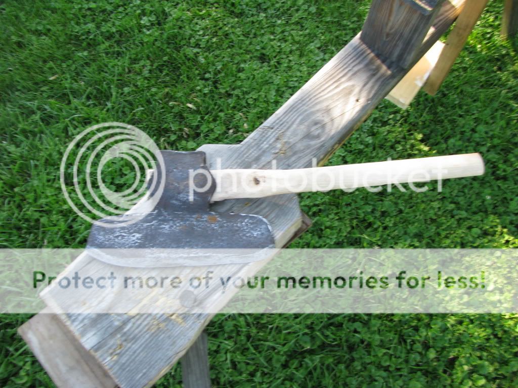 My American Broad Axe, with a 12" face. I just got doen makng that handle. I didn't feel like doing it the 'proper' way and waiting for a good hickory stave to dry out (which takes like a year) so I just made it out of a bigger handle I bought that was made for a pick axe -the eye of a pick axe is huge, so the was plenty of material to carve it out to fit the broad axe. I hen gave it the bend by clamping it down and pouring boiling water on the wood 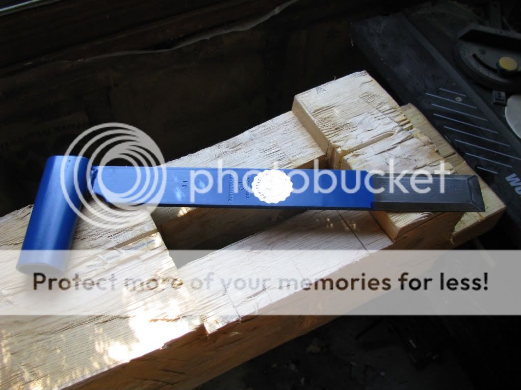 The German Stossaxt, sitting on a hewn ash timber  I like to hew the logs right where they fell, I love working out in the woods I will try to get some better pictures whenever I can
|
|
|
|
Re: Designing With the Daisy Wheel
#23904
06/23/10 02:53 PM
|
Joined: May 2010
Posts: 946
D L Bahler
OP
Member
|
|
OP
Member
Joined: May 2010
Posts: 946 |
The last post was supposed to go on the hewing thread, but the board won't let me edit it anymore for some reason. So here's the post that was supposed to be here instead. If that last one it could be removed, moderator, I would appreciate it bmike, right now I am engaged in a project using all hand hewn timbers, and the actual building of the frame will incorporate hand tools (only?) The idea is to build the thing as they would have done so in Switzerland in the late middle ages or perhaps a little afterward. I'll go ahead and post some pictures of the building as it is now -mostly half-converted logs, and post more up later. That way I can present a progression of Daisy Wheel construction from forest to frame This is an overly-large hickory log that 2 posts are being hewn out of, it was split in half and here the two halves are set up to be finished. Some very rough hewing was done prior to splitting, but a lot of tool marks still remain. This particular log has seen a lot of experimenting! I will try to get some better pictures whenever I can. I have a general layout right now, but I keep making changes to it! So that's the only reason I haven't posted it up here yet. Also I made this the other day so that I could have a good resource to study circular geometry 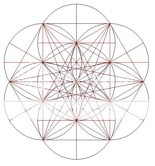
|
|
|
|
Re: Designing With the Daisy Wheel
#23905
06/23/10 03:00 PM
|
Joined: Jan 2008
Posts: 918
bmike
Member
|
|
Member
Joined: Jan 2008
Posts: 918 |
You have to be quick on the edit button! Looking forward to seeing how this translates into buildable plans...
|
|
|
|
Re: Designing With the Daisy Wheel
#23906
06/23/10 03:15 PM
|
Joined: May 2010
Posts: 946
D L Bahler
OP
Member
|
|
OP
Member
Joined: May 2010
Posts: 946 |
Yes, I have the day off so I will probably have time to get something up. Crazy rain causes all kind of problems, I bet we here have had over 6 inches in the past week!
|
|
|
|
Re: Designing With the Daisy Wheel
#23907
06/23/10 03:27 PM
|
Joined: Nov 2005
Posts: 305
timberwrestler
Member
|
|
Member
Joined: Nov 2005
Posts: 305 |
DL,
With center line layout, you would just snap the line longer than the timber, and plumb down from the ends of the timber. To follow up on my earlier question, in my mind, a king post would be centerlined.
With edge layout, an offset layout line is often snapped so that any wonkiness in the timber doesn't get in the way of alignment. Check out the current TF Magazine article that Tim mentions. I'd stick with the top and outside edge for posts, plates, tie beams, rafters, and joists. I have used the bottom of the tie on and English tying joint as the reference on a pergola, where the upper surface wasn't relevant.
|
|
|
|
Re: Designing With the Daisy Wheel
#23912
06/23/10 09:55 PM
|
Joined: May 2010
Posts: 946
D L Bahler
OP
Member
|
|
OP
Member
Joined: May 2010
Posts: 946 |
The gardener's shelter at Cressing Temple  
|
|
|
|
Re: Designing With the Daisy Wheel
#23913
06/24/10 01:10 AM
|
Joined: Dec 2007
Posts: 1,882
TIMBEAL
Member
|
|
Member
Joined: Dec 2007
Posts: 1,882 |
Ken, I am curious if the common rafters in the 1500's building broke on a purlin or went full length?
Tim
|
|
|
|
Re: Designing With the Daisy Wheel
#23919
06/24/10 03:42 PM
|
Joined: May 2010
Posts: 946
D L Bahler
OP
Member
|
|
OP
Member
Joined: May 2010
Posts: 946 |
Alright, I completed my building layout and am satisfied with its design at last. SO here it is  This picture has on it the layout for the cross section (not a bent layout, because this is going to be a German Fachwerkhaus) the floor plan, roof plan and wall elevation. They are color coded so that it is actually possible to tell them apart! Red = Cross section Blue = side elevation Green = Roof Purple = floor plan. If you study the design, you will notice that Joist and rafter spacing is not the same as post spacing, the posts are spaced further apart. The building will be `14'x24', with a first story with 8' walls and a loft area with 4' walls. The doord will be on the long side of the building. The posts are spaced just shy of 5' and the joists and rafters are spaced at 4' The plan is to make a scale model out of 3/4" pine to test the layout scheme and also decide whether or not this design fits the bill for me. The scale is such that 1/8"=1" so that I can easily use 3/4" stock to represent full-sized timbers
Last edited by D L Bahler; 06/24/10 03:44 PM.
|
|
|
|
Re: Designing With the Daisy Wheel
#23920
06/24/10 04:43 PM
|
Joined: May 2010
Posts: 946
D L Bahler
OP
Member
|
|
OP
Member
Joined: May 2010
Posts: 946 |
Another picture.This is a drawing where I have taken the lines from the diagram and used them to create a drawing of the finished building.  Braces and other secondary timbers use the layout lines as their centers in order to keep them properly centered between the primary members. Joists, posts, and rafters use layout lines to mark edges. All other timbers such as top plates and upper sills (something that is used in this style, but isn't used in American or English style framing) are matched up to the posts and joists. This building has characteristic features of Bernese Swiss architecture, such as very wide overhangs (the roof is double pitched so that the overhangs do not reach too far down) and a half-hipped roof (hence the triangular section at the top of the roof drawing) Every single timber in this building is where it is as a result of the daisy wheel, including the slanting braces. The center lines of the braces are marked by lines that extend to connect points on the daisy wheel somewhere off in the distance. The main reason for this is so that the only tools I need to lay out an entire structure are Dividers and a straightedge, no ruled measurements involved whatsoever!
|
|
|
|
Re: Designing With the Daisy Wheel
#23926
06/25/10 01:00 AM
|
Joined: May 2010
Posts: 946
D L Bahler
OP
Member
|
|
OP
Member
Joined: May 2010
Posts: 946 |
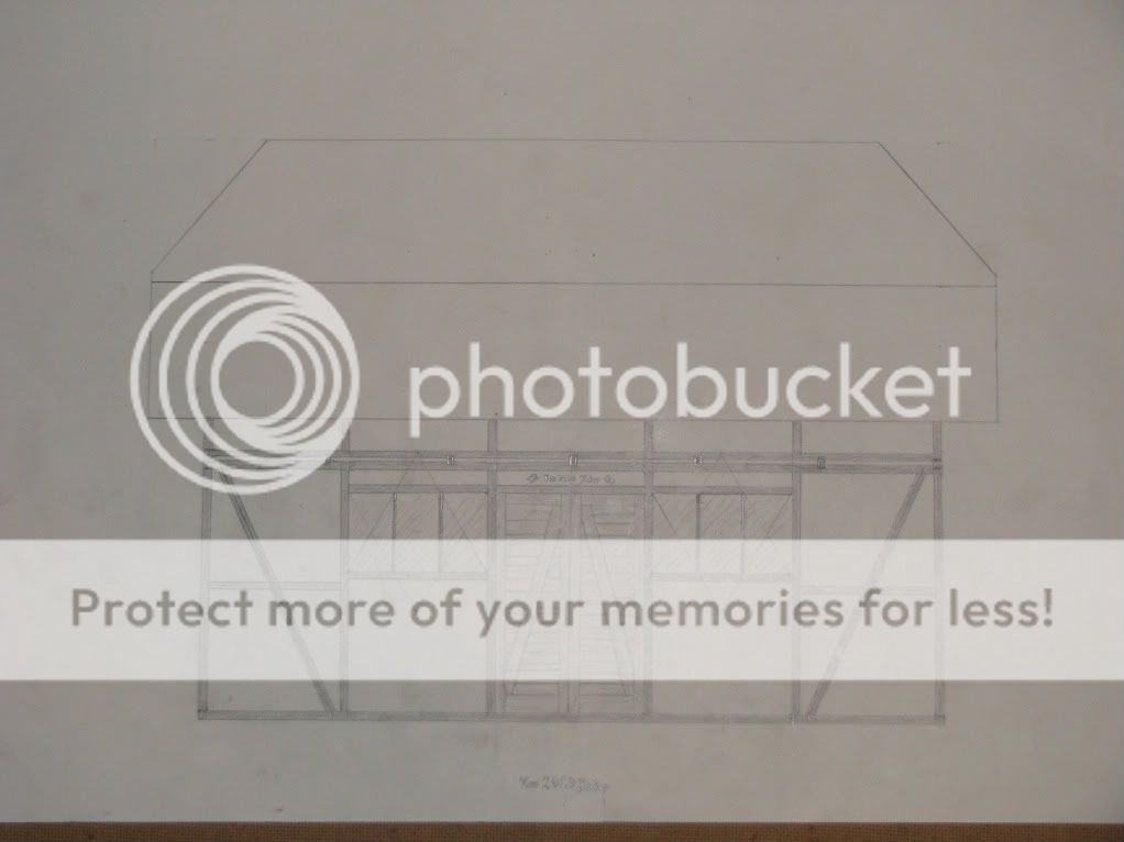 and here at long last is the side view. I left some lines on there as clues to kind of show how I laid out certain features, specifically on the 2 windows. The window is a 1:1.73ish irrational rectangle (ratio of 1:2 short side to diagonal) and is divided into perfect thirds along its length. Try doing THAT with numbers! There will always be something after the decimalTo even establish the window itself required some pretty fancy divider skills. The master radius used to lay out those windows is somewhat bigger than the space between the posts. But triangles and circles will help you find anything! There is a motif above the door, it reads (in German) Im 2010 Jahr (in the year 2010) and is flanked on either side by the Bern Bear. The picture shows the motif on the plastered region above the door, that is an error. It should be carved into the lintel instead. The intent at this point is to cover the roof with red or blue clay roofing tiles (both red and blue clay are available locally, fortunately) in order to keep with the Bernese Swiss style and tradition. This building is my proof of concept for the daisy wheel and general divider layout. at 14'x24' it is larger than any other daisy wheel project I have yet read about. I have got this far without using a ruled measuring device. The next step is the construction of a scale model
|
|
|
|
Re: Designing With the Daisy Wheel
[Re: D L Bahler]
#23927
06/25/10 02:23 AM
|
Joined: Jan 2008
Posts: 918
bmike
Member
|
|
Member
Joined: Jan 2008
Posts: 918 |
To even establish the window itself required some pretty fancy divider skills. The master radius used to lay out those windows is somewhat bigger than the space between the posts. But triangles and circles will help you find anything!
...
at 14'x24' it is larger than any other daisy wheel project I have yet read about. I have got this far without using a ruled measuring device.
With all respect, as I'm interested in how this develops and your process for it - where do you see yourself making changes when function of a space deem the daisy wheel incompatible with the requirements of the program? Or to what extent (as you mention with the windows above) - do you have to gyrate and spin and draw to come up with some geometry that comes from the various rules you've set up for yourself? What is the head height of the windows? Is it relational to the wheel's geometry - or the people or person who will look out of those windows day in and day out? Are they keyed to a view - relating to the outside world - or is this being designed as an object - to simply sit in its environment with its own self contained logic and little relation to the logic of the views / air / sun / wind / etc. around it? And, not to pick - but I find it odd that you describe the building in feet, yet go out of your way to claim that you won't (or haven't) yet used a 'ruled' measuring device. Its cool in a proof of concept sort of way - but is it practical? And why is it 14' x 24'? Wouldn't you describe it with the same language as the wheel...? It seems a disconnect, and I'm not sure how the relationship of 14/24 is derived from the geometry. Is this the footprint you need for the building to do what you want - and then you develop the further geometry from those proportions? Or is 14x24 what happens when you overlap your circles at a particular scale?
|
|
|
|
Re: Designing With the Daisy Wheel
#23928
06/25/10 03:13 AM
|
Joined: May 2010
Posts: 946
D L Bahler
OP
Member
|
|
OP
Member
Joined: May 2010
Posts: 946 |
I described the source and reason of the foot measurements in an earlier post. Basically the reason for that is so that my mind, which is trained in the logic of feet and inches from my childhood, can better envision the finished structure. I set the radius of the circle to 4" so that the wheel would yield imperial measurements, and this ensures that the relative sizes and locations of windows and doors will also be practical. The exclusion of the ruler applies when setting out the design so that I can be assured that geometry rules the day.
In the windows pictured above, the height of the bottom is a little over 4' (the cross beams mark the midpoint of the 8' walls) But they were set up to align with the top of the door more than anything else. However, the window placement on this drawing is not necessarily final placement, I may instead set them so that they sit atop the cross beams (I don't remember the term for these offhand, but it's something in German) Part of the consideration for window placement has to do with the sun. Together with the wide overhangs, I would like for the windows to accept direct sunlight during the winter when the Sun is at a low angle to the horizon, and accept indirect light in the summer when the sun is higher in the sky. That's part of the reason for the somewhat higher placement they have right now.
As far as making changes to fit requirements of real world applications, I deal with this partially simply by having the master radius for the circles set to a measurement of inches. This does yield mostly standard measurements, but it also yields a few irrational numbers as a result of circular geometry.
Why 14x24? Well, because it was set so that the first floor ceiling height would equal 8 feet, this distance is also equal on the diagram to the radius of the circle. The length of the building is equal to 3 radii, or 24 feet. The rectangle that the floor plan is set to is a special daisy wheel rectangle that has a proportional of 1:2 of the length of the short side and the length of the diagonal. Using the Pythagorean Theorem we can find out that the proportional length of the long side would therefore be equal to the square root of 3, which is an irrational number close to 1.732. On the diagram, we know the length only of the long side for certain, which is 24 feet. so 24 feet is equal to the square root of 3 times the length of the short side, so the short side's length (according to my scientific calculator) is an irrational number close to 13.8564, which I have been rounding up to 14 (it is very close to 13 7/8, which would be 13.875, which would be 13' 10 1/2") So that's why! By the way, can you guess I hated math in High school?
We find references here and there to medieval English buildings whose layouts reflect daisy wheel proportions, but also whose measurements match medieval standard units such as the rod. It would seem that the medieval carpenter set his compass to a known measurement. (That's actually where I got the idea) And that makes sense, by doing so you ensure that things are going to come out the size you want them. It also makes it a whole lot easier to figure out how much you need to scale things up from the drawings to make a full sized building. So I guess I wasn't quite right saying I used no ruled measurement, I used 1, and from it all other measurements are derived. So you could say all of my measurements are derived geometrically from 4" I wouldn't go any bigger than 4", and I think 3" or 4" are the best sizes to use, because they both can be used to find useful multiples of feet and fractions of feet. So My quest with a daisy wheel design is to produce a building that will fit with the system. The structure I am working on does that, I believe.
By the way, the reason I don't use a ruler once I've started the design is not because I am morally opposed to rulers or anything like that, it because by doing so I would not come up with something that would transfer as well into the real world, and also doing so would actually be harder than finding things by spinning the compass. Once you start with the system, it doesn't make much sense to try to superimpose some other system over it. For example, would it make sense to design a building starting off with feet and inches, and then at some point switch over to metric? If you start with the imperial system, you've got to stick with it for the whole project or things just won't match up right. It's the same thing, if you start with the daisy wheel then I think you need to stick with it or things just won't match up.
This line of reasoning, however, can run into some flexibility in the area of interior layout. If my building's overall measurements come out as feet, then I feel like it's OK to divide off rooms and such with feet. I will have to experiment some day to see how well you can accomplish that with the daisy wheel though, so far I have yet to see it used or try to use it for any complicated structure.
I plan on creating a conversion scale on my drawing, if nothing else than for kicks and giggles. The point of which would be to get an idea at the size of some of my proportions, and see just how many of my measurements actually come out to be feet and good inches. I suspect most of them will, but we shall see once
|
|
|
|
Re: Designing With the Daisy Wheel
#23929
06/25/10 03:30 AM
|
Joined: Jan 2008
Posts: 918
bmike
Member
|
|
Member
Joined: Jan 2008
Posts: 918 |
DL -
Thanks for the long reply...
While the math and proportions all make sense... I guess I'm more interested in how the geometry meshes with real world program - room sizes, door sizes, bathroom sizes, etc... (and we haven't talked about mashing code requirements into this...)
RE: the windows - have you studied the sun and orientation? Does wheel geometry conveniently make placement so that winter sun can warm the interior and you can be shaded by summer sun? Was the overhang length chosen by the wheel or by sun angle and location on the globe?
I've come at design from a very different side of the problem - orientation / use / program... and then the limits of site / geometry of various materials are used to affect the overall shape. As someone with an art / sculpture background who drifted to architecture - proportion / limits / systems are fascinating to me... hence my questions.
|
|
|
|
Re: Designing With the Daisy Wheel
#23937
06/25/10 10:25 PM
|
Joined: May 2010
Posts: 946
D L Bahler
OP
Member
|
|
OP
Member
Joined: May 2010
Posts: 946 |
Long reply... yeah I tend to do that now and then!
As for windows and doors I would say this: If you are going to use industry standard windows and doors, then there is no need to lay them out with the wheel at all. I laid out my windows because I plan on making my own, and I like the proportions of that particular window. I don't see any difficulty in framing in a standard window or door.
I can't say for certain, but I would guess that you could use the wheel just fine to find room sizes if you wanted. That said, there's no reason at all why you would absolutely have to. The wheel may be the most useful in laying out the overall proportions of a building, after that you could use a measuring tape all you want! Unless you are doing like I am and am making a point to use only medieval techniques and methods throughout. To use the wheel for everything may have little real value beyond novelty or a sense of accomplishment.
The roof overhang on my building was not calculated based on location, It was designed as it was to emulate a specific architectural style.
Keep up the questions, bmike (and others too) these are the things we need to ask!
|
|
|
|
Re: Designing With the Daisy Wheel
#23939
06/26/10 12:37 AM
|
Joined: Dec 2007
Posts: 1,882
TIMBEAL
Member
|
|
Member
Joined: Dec 2007
Posts: 1,882 |
Speaking of tape measures... I use a tape measure on my building. It is based on the daisy wheel but converted to 3/8 = 1' and then to full size. I did not walk the dimensions off with dividers on the full scale building, just on paper. So, it is not true to the wheel as D L's plans are. I am confident it would all walk off, I tested some lengths and they were the same. I used a story pole for other aspects as well, something you would do once walked off lengths are made. 4 large post/braces with a radius cut into them was swung off with a large full size stick with a screw on one end and a notch for the pencil on the other. I find it fun to see how the daisy wheel can answer many questions within a building. I often find building dimensions just picked out of a hat and subject to change or based on the store bought material. A response I tell myself over and over is the wheel made the decision and that is that, it can't be changed. It kind of takes the personal opinion out of the equation. Here is the facebook page with some photos of the building, it was cold back then. It is hard to see, on the post/brace you can see a scaled daisy wheel scratched onto the face. http://www.facebook.com/photo.php?pid=11138693&id=420924555573 Tim
|
|
|
|
Re: Designing With the Daisy Wheel
[Re: TIMBEAL]
#23941
06/26/10 02:09 AM
|
Joined: Jan 2008
Posts: 918
bmike
Member
|
|
Member
Joined: Jan 2008
Posts: 918 |
A response I tell myself over and over is the wheel made the decision and that is that, it can't be changed. It kind of takes the personal opinion out of the equation. I don't know what to do with this, especially seeing as in the past on the forums there were threads criticizing 'computer' aided design that hinted at the notion that the computer was making the decisions for the designer... a daisy wheel, in this application, is that mindless computer, making decision for the designer, without regard to function, use, materials at hand, solar orientation, etc. I guess that was my point in questioning DL about his windows. DL - I think it is great that you plan on making your own windows, but the point is irrelevant as most windows can be had in any shape and size you want from many manufacturers. What I was driving at was the location and size of the windows in relation to use of the building - were heights calibrated to occupants eye level as they might be related to exterior views? Did solar orientation play a role, if relevant, to window location and design? etc. etc. - or did the location and size come about by some geometric convention derived from the use of the wheel (which is what you did)... As I mentioned - I'm fascinated by all systems of scale / layout / proportion. I'm curious where one draws the line at which decisions are 'blind' to the system, (be it 4x8 sheets, 4x24 panels, 8x8 posts, golden sections, wheel geometry, etc.) and which are made by the designer - in reference and respect to all those other factors that may be important (or not).
Last edited by bmike; 06/26/10 02:11 AM.
|
|
|
|
Re: Designing With the Daisy Wheel
#23942
06/26/10 03:12 AM
|
Joined: Dec 2007
Posts: 1,882
TIMBEAL
Member
|
|
Member
Joined: Dec 2007
Posts: 1,882 |
A set of dividers is about as close as you can get to a democratic tool. Anyone can use it, it comes with a low cost or even free and or you can make your own. This is what I find attractive about the dividers.
I can not say that for the computer.
Tim
|
|
|
|
Re: Designing With the Daisy Wheel
#23943
06/26/10 03:42 AM
|
Joined: May 2010
Posts: 946
D L Bahler
OP
Member
|
|
OP
Member
Joined: May 2010
Posts: 946 |
bmike, the placement of the windows was a result of the wheel, but it's not as if the wheel gives me an option of 2 or 3 heights to place the window. There are probably hundreds of different places I could put the thing by using intersection points, I chose these paricular location because it was aesthetically pleasing, and because that particular location seemed reasonable. The width and height of the windows was not laid out according to the 'master wheel' at all, but rather it was made to fit the space between the posts and still create the desired proportions. If you look closely at the drawing, you can see each window is slightly overlaid with a star of David, that is how I determined its proportions. I made a new circle for each window. In reality when doing this on the completed structure, the doors and windows will be set inside of frames to keep them at consistent heights and widths, so as to avoid the irregularity of the posts. You are right that in most projects all of this would be unnecessary, but like I said it's just something I wanted to do in keeping with the medieval theme of the design. Somehow having vinyl clad Andersen Windows or some such would just be out of place, although certainly a whole lot easier!
The wheel as I use it really is not as commanding as it may seem. It's no different than if you would use graph or grid paper to draw a building design. There you are stuck with the lines of the graph, so how is being stuck with the literally thousands of lines that the wheel can give me any worse or more blind? Look at my layout drawings with the wheel and its lines in the background.
By the way, I foresee the question arising of if you have these supposed thousands of possibilities, how is geometry any better, or how are you staying geometric, or some such. The answer to that is quite simple, some lines are better than others! The best lines of the wheel, what I call 'Category 1', are those lines that are simply connectors between circle overlap points -the lines you see drawn on my basic diagram- especially those that connect opposing or reflected points. These lines are the ones I like to use for the basis of my designs "Category 2" lines are still good, these are the lines made by intersection of 'category 1' lines. These are what I like to use, for example, to establish roof lines. 'category 3'lines are those that are formed by connecting intersections of category 2 lines, or intersections of category 1 lines and circles. Category 4 lines are formed by the intersection of building lines (when they don't fit into a previous category) and any other category 3 or higher line. And the list goes on and on... It sounds complicated but it's really all quite natural and fairly obvious. That's the system I use, which I think yields a good combination of limitation (because limitation yields strength) and freedom.
And that last point is an important point Limitation yields Strength and I could also say limitation yields beauty
|
|
|
|
Re: Designing With the Daisy Wheel
[Re: TIMBEAL]
#23944
06/26/10 11:29 AM
|
Joined: Jan 2008
Posts: 918
bmike
Member
|
|
Member
Joined: Jan 2008
Posts: 918 |
A set of dividers is about as close as you can get to a democratic tool. Anyone can use it, it comes with a low cost or even free and or you can make your own. This is what I find attractive about the dividers.
I can not say that for the computer.
Tim Tim - perhaps you should have been more clear on this distinction in previous posts. It would have changed the conversation. DL - Yes, there is power within limits and a fascinating book of similar name. Thanks for the thoughtful replies, it has shed some light on how you are using the wheel. And - its a cool study - my questions were intended to sort out the why's of how you were getting your results.
|
|
|
|
Re: Designing With the Daisy Wheel
#23950
06/27/10 03:12 AM
|
Joined: May 2010
Posts: 946
D L Bahler
OP
Member
|
|
OP
Member
Joined: May 2010
Posts: 946 |
Any system we use to design a building is a set of limits, and from those limits a 'normal' arises. Normal, after all, is a relative term for something that conforms to the standard limits in a given system. A 'normal' door, for example, would conform to the standard industrial sizes of 2'8, 3'0, etc. anything other than that would be unusual
So we could assume that the Daisy Wheel creates its own normal that may or may not conform to the imperial or metric systems' normal. But I suspect that we could easily get things *close enough* to escape the building inspector's scrutiny. My building, for example, is close enough that I could call it a 24x14 and not have any problems with the system, even though it is about 1 1/2 inches off from that. The irrational numbers that the wheel is going to inevitably give you can easily be represented as real numbers for the sake of those of us that do not think geometrically, even if we step them off somehow when we actually lay out and join the timbers (whether it be with dividers or rods, or whatever system you choose to use). That is the reason that I have referred to my building as 24x14, even though that is a little bit inaccurate (a hair more than 1 1/2 inches off)
I was thinking of the problem of glass for my windows, for example. What am I going to do about that, I can't just send out to glass guy and ask for a piece cut the square root of some un-square-rootable number, or give him a set of dividers and ask him to come up with the glass size for me geometrically? But it would work just fine if I were to give him a size measured to fractions of an inch. What's important is that the frame for the window glass, which I will make myself, line up geometrically. It doesn't matter if the glass has a 1/8 inch of room or so inside the frame, where only bugs and dust and architectural historians a hundred years from now are going to be able to tell that I 'cheated'.
|
|
|
|
Re: Designing With the Daisy Wheel
#24007
07/03/10 05:43 PM
|
Joined: May 2010
Posts: 946
D L Bahler
OP
Member
|
|
OP
Member
Joined: May 2010
Posts: 946 |
http://www.traditionaltimberframe.com/V1_0/index.php?mod=frenchscribe&ac=procedureFor all your scribing needs, this describes the process in detail. After having researched it, It seems that the French Scribe, or at least the alignment of the timbers to a full-scale ground plan (which is in fact only part of the whole french scribe process) is in fact a method used across Europe. I have seen many pictures of German carpenters laying out buildings along full-scale ground layouts. I have also discovered a solution to layout on irregular ground. The method shown in that link is designed to be used on a flat shop floor, however that is not the way it is always done. Historically the layout would often be created exactly where the building was to be raised. The solution I have seen used is to take boards and lay them out on the ground with chalk lines down the middle, squaring the lines using the Pythagorean Theorem instead of using a giant compass. The layout can then be made with lines snapped on a series of boards. The advantage to this is that it is easier and more accurate to step off measurements on flat boards than on uneven ground, and with this method you can lay out the structure without needing to have a shop floor that big. This all reminds me, at the base of the great pyramid in Egypt a series of holes were once discovered that, when connected, supposedly create an exact elevation of the pyramid, complete with the details of the internal chambers and all that. In other words, the exact geometry of this enigma was established with a plan, and the plan seems to suggest that the multiple chambers were not, in fact, the result of a Pharaoh who kept changing his mind. It would appear that this method of scribe layout is incredibly ancient. I wonder if such a system was used by the ancient Greeks to build their amazing temples and amphitheaters
|
|
|
|
Re: Designing With the Daisy Wheel
#24008
07/04/10 12:43 AM
|
Joined: May 2010
Posts: 946
D L Bahler
OP
Member
|
|
OP
Member
Joined: May 2010
Posts: 946 |
I created a full scale layout today of my building designed with the daisy wheel, the primary reason for this was to test methods and concept, and to have some practice doing such a layout when it comes time to make the building (I would hope to be able to get started by this fall, but don't realistically expect that to happen til the middle of next summer) My final layout is going to be made right on the ground where the building is to be erected, partially so that this personal project does not occupy valuable floor space, and also in keeping with the medieval spirit of this project -I have read that all buildings built prior to the industrial revolution were done like this, lade out and cut right there on sight, and that shop layout is a modern development. I started out by using boards with lines chalked on them to establish a right angle. I did this by using the Pythagorean Theorem. I measured down 1 line 3 units, down another 4 units, and then had a third board with 5 units marked off on it, then manipulated all 3 boards until the 3 segments matched up to form a perfect 3-4-5 right triangle, thus establishing the right angle.  next I established the rectangle of the floor plan with more boards, although in hindsight the boards were necessary only for establishing right angles, and were not needed after that point. 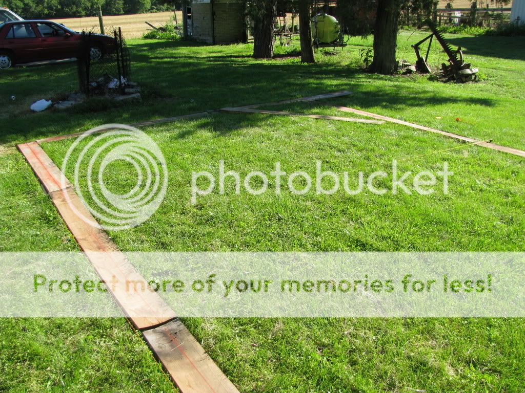 While creating the layout, I made a series of Rods based on dimensions on the daisy wheel diagram. These rods were of various proportions, with their proportions clearly marked to avoid confusion. They were at least 4 times the scale of the drawing and some used for smaller measurements were the full 24 times the drawing lines. These consist of pieces of wood with 2 20d spikes driven through at exact points determined by the dividers, and the points of these then carefully aligned to ensure they too are the the same exact distance, Any error here would only compound over time. The spikes were driven all the way through, so that they would be long enough to stick into the ground so that I would not need boards everywhere. The ground at this particular spot is flat enough to do that and still be accurate, and measurements taken afterward confirm the accuracy of this method. 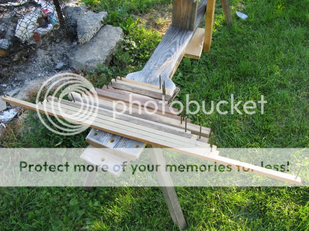 I proceeded to lay out all important reference lines, using my trammel point compasses to step off various measurements, all the while discovering how frequently and beautifully things repeat and relate to each other. If I had known this, I could have gotten by with maybe half as many rods!  View of roof geometry layout  closeup of roof geometry  pitch change, plate, post and tie right click on pictures and click 'view image' to see a larger view, details don't show up very well otherwise. more pictures at: http://s538.photobucket.com/albums/ff345/HiddenOrder/Timber%20Framing/I made 1 or two minor adjustments to some of my measurements when I switched methods for stepping them off. I decided to see how well I would fare by not measuring 1 end of the floor plan but trusting in the accuracy of my right angles and lines, just to see how well the system worked, the result being that it was accurate to within 1/2" in 24' of length, which is very good! At one point I had to step off to find the center point of the end walls, and I was very pleased at how accurate it came out having not measured 1 wall at all. (I did then adjust that measurement so that it would be perfect) I was very pleased at how accurately I could make right angles using this method, and was especially pleased that I was able to complete the entire layout to very exacting standards of accuracy completely by myself. Needless to say, I am very excited to begin laying out the joinery! I am very satisfied with these results, and for me at least it proves the concept of this method of daisy wheel layout. The full scale layout allows you to see things that aren't immediately evident on paper, and the laying out process gives you a much better understanding of the proportions involved. It also revealed another thing to me. The rulers that I used to set my dividers are supposedly accurate to within 0.005" or maybe it 0.0005", whatever it is it's a very tight tolerance. My good old Stanley measuring tape, however, does not reflect this same degree of accuracy. Having set my dividers to 4", the slight almost unnoticeable difference between the two comes out to a difference of a little over 1" along the 24 foot long wall. So unfortunately I won't be able to measure proportions and relationships as easily as I had hoped.
|
|
|
|
Re: Designing With the Daisy Wheel
#24009
07/04/10 01:06 AM
|
Joined: May 2010
Posts: 946
D L Bahler
OP
Member
|
|
OP
Member
Joined: May 2010
Posts: 946 |
Correction, the long wall was 24 5/8" long according to Stanley, so the difference between measuring devices comes out to 5/8"
|
|
|
|
Re: Designing With the Daisy Wheel
[Re: D L Bahler]
#24045
07/13/10 08:48 PM
|
Joined: Jun 2007
Posts: 195
frwinks
Member
|
|
Member
Joined: Jun 2007
Posts: 195 |
Hi DL, please keep us posted on your progress... your threads are some of the more exciting ones on this forum  re windows... I designed one of our feature windows with the wheel, the window co. simply asked for a template and are building it based on it vs. measurments. The guy was amazed to see the wheel still in use, we had a good long conversation about it...
there's a thin line between hobby and mental illness
|
|
|
|
Re: Designing With the Daisy Wheel
#24059
07/19/10 11:05 PM
|
Joined: May 2010
Posts: 946
D L Bahler
OP
Member
|
|
OP
Member
Joined: May 2010
Posts: 946 |
Perhaps a title for this post could be Moving Beyond the WheelIn studying this system and working out the various aspects of my design, I think that there is much more in the realm of circular geometry than what the wheel itself shows you, at least right off. I remember once having read a description of how Canterbury cathedral was laid out according to the system of Ad Triangulum. This, as I understand it, is a system of laying out rectangles by means of squares. This cathedral was limited by the narrow frontage of the lot it was built on, and so this measurement was used to derive all other measurements, down to the placement of the altar within the chapel. Essentially this was done by taking that measurement and various sections of it and drawing a series of circles on the ground to create the plan. Below are examples of the Euclidean Geometry of Canterbury Cathedral  The Geometry of Lanfranc’s Cathedral 1070-1096/1120  The Geometry of the Choir of 1120 
|
|
|
|
Re: Designing With the Daisy Wheel
#24060
07/20/10 03:01 AM
|
Joined: May 2010
Posts: 946
D L Bahler
OP
Member
|
|
OP
Member
Joined: May 2010
Posts: 946 |
|
|
|
|
Re: Designing With the Daisy Wheel
#24062
07/20/10 10:27 PM
|
Joined: May 2010
Posts: 946
D L Bahler
OP
Member
|
|
OP
Member
Joined: May 2010
Posts: 946 |
 Geometry of the Hagia Sophia, Constantinople The current dome was built when the original collapsed after an earthquake, and its design was based on the geometry of the building it was built upon. This shows Ad Quadratum geometry The Ad Quatratum system:      Ad Quadratum was apparently considered to be more sacred than Ad Triangulum because it yielded the 8-pointed 'star of Christ' instead of the 6-pointed star of Ad Triangulum. Sacred Geometry (that is, the geometry of Cathedrals and other sacred spaces) seems to have employed Ad Quad. more than ad Triang. The daisy wheel can be considered a form of Ad Triangulum, as it employs the same principles and yield the same geometry.  Even the Pagan-built Pantheon in Rome employs this ancient Euclidean Geometry
Last edited by D L Bahler; 07/20/10 10:36 PM.
|
|
|
|
Re: Designing With the Daisy Wheel
#24063
07/20/10 10:50 PM
|
Joined: May 2010
Posts: 946
D L Bahler
OP
Member
|
|
OP
Member
Joined: May 2010
Posts: 946 |
"There will be those who question the need to begin every architectural geometric design with a circle. There are two cogent reasons. The first is that the architect is aiming in his design to bring Heaven down to earth and Heaven’s geometry is circular. The second reason is even more cogent. It is irrefutable. The fact is that it is impossible to construct a true square, or octagon or octagram or hexagon or hexagram without a pre-existing circle. Even an equilateral triangle requires the intersection of two arcs that is simply in essence the intersection of two circles."
|
|
|
|
Re: Designing With the Daisy Wheel
#24067
07/21/10 12:40 AM
|
Joined: May 2010
Posts: 946
D L Bahler
OP
Member
|
|
OP
Member
Joined: May 2010
Posts: 946 |
Let it be granted:
i. That a straight line may be drawn from any point to any other point.
ii. That a terminated line may be produced to any length in a straight line.
iii. That a circle may be described from any centre, at any distance from that centre.
Euclid's first 3 Postulates
A new point is determined in Euclidian geometry exclusively in one of the following ways:
Having given four points A,B,C,D, not all incident on the same straight line, then:
Whenever a point P exists which is incident on both (A,B) and on (C,D) that point is regarded as determinate.
1. Whenever a point P exists which is incident both on the straight line (A,B) and on the circle C(D) that point is regarded as determinate.
2. Whenever a point P exists which is incident on both the circles A(B), C(D), that point is regarded as determinate. The cardinal points of any figure determined by a Euclidian construction are always found by means of a finite number of successive applications of some or all of these rules 1, 2, 3.
E.W. Hobson Squaring the Circle. History of the Problem(1913, 7-8)
The term Euclidean construction is used for any construction, whether contained within his works or not, which can be carried out with Euclid’s two operations repeated any finite number of times (Hudson 1915, 1ff.). -These two operations are the drawing of straight lines and circles according to his postulates
|
|
|
|
Re: Designing With the Daisy Wheel
[Re: D L Bahler]
#24071
07/21/10 04:14 PM
|
Joined: Mar 2002
Posts: 961
Ken Hume
Member
|
|
Member
Joined: Mar 2002
Posts: 961 |
Hi D.L., OK - now here's the real thing :- Daisy Wheel please explain that to me ! Regards Ken Hume
Looking back to see the way ahead !
|
|
|
|
Re: Designing With the Daisy Wheel
#24074
07/22/10 02:31 AM
|
Joined: May 2010
Posts: 946
D L Bahler
OP
Member
|
|
OP
Member
Joined: May 2010
Posts: 946 |
Ken, What and where is that? And what's with all the scratches all over the place?
The figure in the middle seems to be a simple construction according to the Ad Triangulum or Daisy Wheel mode. The outer circle's radius is equal to the diameter of the inner circle, and two arcs of equal size are scribed on it marking 4 of the six points of the daisy wheel. All the scratches make it difficult to make out.
What is this thing? I have no Idea. Maybe it's the work of some geometer musing with his compass, maybe it's a geometric symbol set into the building for spiritual reasons.
Ever think that the use of the daisy wheel could simultaneously have both of its theoretical applications? Even in a single instance?
The daisy wheel was a tool or at least a form of a tool for geometric design, because without the circle you really can't do anything else. At the same time it was a symbol of protection, harmony, or some type of divine blessing. How so? Because to the Medieval mind, geometry was sacred. Geometry was a reflection of the divine, and of the order of Heaven, particularly since Heaven was thought to be circular in nature, with its center at the Godhead.
The Ad Quadratum reflected the sphere of the earth, with the square pointing off to the four corners of the world.
The Ad Triangulum reflected the elemental essence of creation, with the two triangles overlapping to reflect the full alchemical cycle. Plato is said to have had above the door to his academy a sign that read "let no man that is ignorant in the ways of geometry enter here." or some such. Geometry was the foundation of the ancient world and its philosophy, so why would geometric symbols not hold sacred value to these people?
Don't discount the divine...
|
|
|
|
Re: Designing With the Daisy Wheel
#24080
07/24/10 10:04 AM
|
Joined: Mar 2002
Posts: 961
Ken Hume
Member
|
|
Member
Joined: Mar 2002
Posts: 961 |
Hi DL,
Sometimes there are no immediate answers to questions posed and all that could be said is therefore pure conjecture which is certainly not the same thing as hard evidence based fact.
The daisy wheel concerned is on an elm fireplace mantle beam in an Oxfordshire cottage and it might date from the early 1600's. It is not unusual to find such marks but the meaning of same is still not fully understood. Timothy Easton and Laurie Smith are researching these and other types of apotropaic marks.
Regards
Ken Hume
Last edited by Ken Hume; 07/24/10 10:06 AM.
Looking back to see the way ahead !
|
|
|
|
Re: Designing With the Daisy Wheel
#24117
08/06/10 02:57 AM
|
Joined: May 2010
Posts: 946
D L Bahler
OP
Member
|
|
OP
Member
Joined: May 2010
Posts: 946 |
It would be very interesting to hear their conclusions on these things!
I have come to the conclusion that Ad Triangulum/Daisy Wheel geometry is quite a bit easier to use than Ad Quadratum geometry. I suspect that Ad Triangulum or some form thereof may have been the inspiration for scribing daisy wheels all over. The construction of the daisy wheel is, after all, the first part of any Triangulum construction.
I have found that since researching Ad Triangulum and Ad Quadratum, my geometric constructions have become a lot more line oriented. That is, I use lines a lot more than circles any more to establish points.
With these kinds of Euclidean constructions, you also make use of circles of different radii, whereas with a purely daisy wheel construction you just use a single radius, at least at the start. It seems rather confusing, but once you try it things make sense a lot more.
The advantage of Ad Triangulum and Ad Quadratum is also that there is actually some period writing on their use, including instructional manuscripts. Many of these were written when the geometric Gothic architecture began to give way to Classical Revival and other such styles of building and new tools came into play such as the square and the divided rule. These manuscripts were written as an attempt to preserve the then dying (and now dead) High and Liberal Art of Architectural Geometry
|
|
|
|
Re: Designing With the Daisy Wheel
#24118
08/06/10 09:09 PM
|
Joined: May 2010
Posts: 946
D L Bahler
OP
Member
|
|
OP
Member
Joined: May 2010
Posts: 946 |
http://books.google.com/books?id=uSHqAAAAMAAJ&printsec=frontcover&dq=B%C3%BCchlein+von+der+Fialen+Gerechtigkeit&source=bl&ots=_FABRmQscv&sig=8Tp639UHFMaAKZkOxYah4RuxdX4&hl=en&ei=YXdcTMmOGcKnsQbbtvGPBg&sa=X&oi=book_result&ct=result&resnum=1&ved=0CBIQ6AEwAA#v=onepage&q&f=false
this might be useful to some of you. It's in German, Fraktur script at that, so you can't all read it I know, but it does have many useful diagrams. This book was printed in 1486 in Germany by a master builder named Matthäus Roritzer, and it is about Ad Quadratum geometry. It is an instructional manual on how to use this system
|
|
|
|
Re: Designing With the Daisy Wheel
#25101
01/10/11 12:18 AM
|
Joined: Dec 2007
Posts: 1,882
TIMBEAL
Member
|
|
Member
Joined: Dec 2007
Posts: 1,882 |
Hi Jim, I have watched a bunch of his stuff, I like his perspective, and it can get deep, as he suggest. Religious and political, but more to the building side of things, I try to apply it. I just snapped out a 6/12 roof on my floor and in gaining square lines I swung a bunch of half circles, some over lapping and out popped a bunch of fishes bladders, what a mess.
I think a lot could be said about vibrations, much is formed from vibrations, light and color is vibrations. Hold a cat up to a light, while they look for cluster flies on the ceiling, then look into their eyes. The Egyptians had a fetish with cats.
|
|
|
|
Re: Designing With the Daisy Wheel
#25109
01/10/11 01:55 AM
|
Joined: Dec 2007
Posts: 1,882
TIMBEAL
Member
|
|
Member
Joined: Dec 2007
Posts: 1,882 |
|
|
|
|
Re: Designing With the Daisy Wheel
[Re: D L Bahler]
#25111
01/10/11 05:21 AM
|
Joined: May 2010
Posts: 946
D L Bahler
OP
Member
|
|
OP
Member
Joined: May 2010
Posts: 946 |
While I must say I am very wary of any 'New Age' associations with 'sacred geometry' I am fascinated with the medieval, and ultimately platonic, ideas regarding the subject. I think that anyone who wants to give the idea of 'sacred geometry' a serious consideration needs to look at it in a historical perspective. We need to not look at a lot of the modern ideas, which all to often fall into the category of pseudo science, among other complaints I might have to make against them. Instead, we need to study the sources of the great philosophers who shaped the western world. Instead of getting your knowledge from youtube, I would highly recommend a serious study of the works of Plato, Augustine of Hippo, Johannes Kepler, and others from before the so called 'enlightenment' (one of the worst things to ever happen to western society, in my opinion) http://www.skyscript.co.uk/kepler.html Now, all of this is actually quite unnecessary when we are actually designing buildings, that is unless you actually ascribe to the medieval notions of geometry, which I myself tend towards to some small degree. My view is not that geometry brings any sort of heavenly blessing as the medieval man might have thought. Rather, it is that geometry gives you something that is very real and tangible, and that cannot be achieved through any other means. Geometric relations exist in harmony, which means they are naturally strong. Geometry divides a frame along lines that follow the patterns of the natural world. On this topic, I have been developing what could be termed a 'simplified geometry' It is a system intended to be used by those who wish to design houses and other such, rather than Gothic Cathedrals. It is also designed with the intention of being performed at full scale, rather than on paper (although you might use paper to draft the design) because full scale is so much more accurate. To this end, this system is much more line oriented rather than circle oriented. Although circles must be used to create any sort of geometry. The idea of this is that it is considerably harder to scribe giant circles than to connect points over a long distance. This system is designed so that it can be performed with merely a rope, stakes, and string.
|
|
|
|
Re: Designing With the Daisy Wheel
#25114
01/10/11 12:54 PM
|
Joined: Dec 2007
Posts: 1,882
TIMBEAL
Member
|
|
Member
Joined: Dec 2007
Posts: 1,882 |
Nice link, DL, "Frozen music" I enjoyed the read. My apologies for mucking up your thread on the daisy wheel with a U-tube video. It was just a "cat video" anyway, someday it could go viral with 2,462,678 views, and an advertisement to boot. And at additional risk.....more useless u-tube. I hear utubers will watch anything. It is two parts and relevant to the topic at hand. http://www.youtube.com/watch?v=IBvMhpx8Q0Q http://www.youtube.com/watch?v=ye3CUGwe5D4
|
|
|
|
Re: Designing With the Daisy Wheel
#25122
01/10/11 06:41 PM
|
Joined: May 2010
Posts: 946
D L Bahler
OP
Member
|
|
OP
Member
Joined: May 2010
Posts: 946 |
I'm not complaining about Youtube by any means, there is certainly some useful information to be had there.
Im just encouraging people not to use things like Youtube and Wikipedia as primary sources. They are great for pointing you in the right direction to do some serious research or introducing you to a new topic, but there is no guarantee of their accuracy. But go ahead and link videos, they are interesting and do point out things we may not have found otherwise.
Now back to geometry...
It is interesting to think of geometry in terms of celestial harmony, and even music. We have the Musica Universalis, the music of the universe. But we also have the the Harmonius Mundi, the harmony of the earth. The former is often represented in the grand scale, such as with Kepler's models with the platonic solids. The latter is thought of in a minute scale, and is in the middle ages manifested by geometry. Geometry, one could say, IS Harmonius Mundi. It is the harmonic relationship of all earthly things.
This is interesting, because we know that vibrations can destroy things. A constant vibration in many cases can do much more damage than a sudden blast of much greater force. We have the example that many wooden bridges restricted travel across them to a walk, as the harmonic rhythm of a horse's trot could lead to the destruction of the wooden frame. We also have the example of the Tacoma Narrows Bridge, where the wind achieved the exact speed to cause the bridge to vibrate in such a way that it shook apart. The bridge had been subject to much higher winds, but this particular wind was at the exact right speed and angle to cause it to vibrate in a damaging way.
In the same way, we recognize when designing floor frames that they must be designed in such a way that their harmonic vibration is well outside of the range that might be caused by normal human activity, lest they fail quite unexpectedly.
SO one could take these ideas and theorize that geometry divides a frame along lines of harmony. As a string divided in perfect geometric ratios creates perfect notes that resonate in harmony with each other, so the it is with the geometric frame. We might think of our timbers as great strings being plucked to create a certain resonance. If we divide these string arbitrarily we will create dissonance. Think of the violin with no frets, we must put our finger at the exact right spot to create a harmonious note. Otherwise we have dissonance. This dissonance, even if very minute, is immediately noticeable to he human ear and will ruin the music. You cannot pick a spot to place your finger without the knowledge of where it should go.
And so it may be with timbers. IF we arbitrarily choose a location to place a post or strut or brace or whatever, then we may indeed create geometric dissonance. But divide the the frame, indeed the building as a whole, along geometric means, then we achieve 'Harmonius Mundi' And what better method is there to stand against the forces of nature than with nature itself?
What geometric dissonance could be I am not entirely certain. It could be an aspect of vibration, and poor choice of division leads to poor handling of vibration, or for that matter any other natural force (it is the natural forces over long periods of time that are the most damaging). Or it could be a matter of strength, rather than weakness. That is to say, poorly divided frames don't weaken any of the members, but rather by doing so you are not gaining an aspect of strength that is available to you. A dissonant frame could indeed stand, as a dissonant not doesn't cause the instrument to shake apart, but it would not stand for long I suspect.
Dissonant intervals are used to stir emotion in music. The tritone, for example, is a musical interval that will immediately cause a feeling of discomfort, anxiety, and even to some degree anger. It leaves you in anticipation of another note, but if it goes unresolved than it is unsettling. Total dissonance, where notes have no harmonic relationship whatsoever, is terrible, and we cannot stand to listen to it.
In a similar way, dissonance may leave the geometry of a building in anticipation. It expects something else to come along, but if it is not thee than the frame is left in unequal tension. I propose that a frame must be in balance. Not reflective symmetry, but harmonic balance. This means that harmonic relationships must be balanced out, as in music you do not hold the tritone without resolving to the fourth or the fifth, or you do not end a song on a note that is not suitable. In a frame you cannot have unbalanced relationships.
Perhaps a deep study of the music theory of those before the creation of the modern tempered western scale would tell us a lot about building and engineering...
This could all be crazy, but it could all be something huge. If this theory is right, than it is everything.
I would love to be able to test it, but I do not have the resources.
Last edited by D L Bahler; 01/10/11 06:55 PM.
|
|
|
|
|