|
 Re: Shop Project
#25767
03/03/11 06:05 PM Re: Shop Project
#25767
03/03/11 06:05 PM
|
Joined: Aug 2009
Posts: 306
Cecile en Don Wa

Member
|
|
Member
Joined: Aug 2009
Posts: 306 |
Hello,
Then you will certainly be needing your zunftkleidung.
Greetings,
Don Wagstaff
|
|
|
|
Re: Shop Project
#25768
03/03/11 06:39 PM
|
Joined: May 2010
Posts: 946
D L Bahler
OP
Member
|
|
OP
Member
Joined: May 2010
Posts: 946 |
Nein, sie tun nicht so in der Ländlichen Schweiz.
|
|
|
|
Re: Shop Project
[Re: D L Bahler]
#25776
03/04/11 08:40 AM
|
Joined: Aug 2009
Posts: 306
Cecile en Don Wa
Member
|
|
Member
Joined: Aug 2009
Posts: 306 |
Hello, You would be most likely to see a Swiss carpenter today wearing a baseball cap a t-shirt and some of those big ol' shorts. I have noticed that for some reason, who knows maybe with connections right back to old fashioned guild practices, that all through Western Europe every trade or even manual profession, for example farmers, seem to have their own standardized dress elements. Here in Holland the farmer - men and women - wears a light blue cover-all. And the dairy farmer has a funny green hat. Of course these days it's not strictly adhered to, but in more formal situations, these old group identifications are clear. Last week I attended a wood auction and everyone there seemed to be wearing dark green which was always the uniform of the woodsman's professions. Here's a picture of some fine young rural Swiss carpenters I plucked from the internet Greetings, Don Wagstaff
|
|
|
|
Re: Shop Project
#25777
03/04/11 12:43 PM
|
Joined: Dec 2007
Posts: 1,882
TIMBEAL
Member
|
|
Member
Joined: Dec 2007
Posts: 1,882 |
I have no problem understanding the scaling up, how the size and shape of the building is developed, and the history behind it. This leaves me with how the joinery will be executed? I don't see it being mill ruled, or square ruled but it may be possible. One of the various scribe methods, I am left to guess at. So, how will the joinery be laid out?
|
|
|
|
Re: Shop Project
#25781
03/04/11 04:16 PM
|
Joined: May 2010
Posts: 946
D L Bahler
OP
Member
|
|
OP
Member
Joined: May 2010
Posts: 946 |
The joinery is not immediately evident from the drawings, when taking joinery into account the geometric lines in the end come out only to approximates in many cases. The method will be to establish certain timbers as primary and have them fit the geometry exactly, and have other secondary timbers fit in as best as they can considering.
Being made of hewn timbers, mill rule is impossible. I will be using a scribe method.
Mill rule and square rule are both American inventions, and to this day a lot of Central European carpenters apparently don't trust a milled timber to be accurate, and as such will still scribe their joints.
Don, historically the carpenters of the remote Swiss villages would have had no association with any sort of guild. Often times there wasn't a formal carpentry trade at all. There would have been those recognized as being master carpenters, and there is much surviving work showing just how masterful they were, but they would often by occupation have been largely farmers. Such was village life in pre-industrial Switzerland. Add to this the fact that as an Anabaptist I would have been forbidden by law from being in the guilds, a practice that survived in the Canton of Bern until very recent times.
The biggest result of the lack of a guild structure among the rural carpenters is the amazing diversity of building techniques, especially true of the Canton of Bern. Building styles can totally change from one valley to the next, because the people in these valleys would have had very little and irregular contact with each other.
In Switzerland there is a very strong tradition of dress as well, but not so much as a way of identifying your trade. Rather they identify themselves with their people, with their village. There is a famous panorama in the city of Thun of that city in the 1800's, I have heard that many local Swiss can look at that picture to this day and tell you what village everyone it it is from based on the way they are dressed.
|
|
|
|
Re: Shop Project
#25785
03/04/11 09:33 PM
|
Joined: May 2010
Posts: 946
D L Bahler
OP
Member
|
|
OP
Member
Joined: May 2010
Posts: 946 |
Tim, to further clarify the issue of joinery (i didn't have time earlier to go into intimate detail)...
I have read it explained this way when referring to the structure of a timber frame: there is an ideal layout that would exist according to engineering if the various pieces were all on continuous whole linked together, but in the real world you must deal with joints and their specific characteristics as well as the nature of wood to be weaker around a joint. This causes 2 things to happen: 1 your 'ideal' frame layout is modified to fit the style of joinery you will use, and 2 the exact positioning of certain framing elements will be slightly modified to account for the inherent weaknesses in joined wood.
The lines on my drawing reflect the theoretically ideal locations of the timbers according to the system of joinery and frame layout I will be using, but certain of the timbers will not fall exactly along these lines due to such realities as timber dimensions and joint weakness.
Those timbers that are chosen as primary framing elements will be aligned directly to the lines, either with the lines marking a center of an edge. In most cases the lines will mark an edge, i.e the wall lines mark the smooth inside face of the walls and the joist lines mark the smooth upper face of the floors; this ensures that those parts of the building that most need it will have a straight even surface.
The procedure here would be to pick a reference face on the primary timbers, this face may in some cases be the nicest looking faces (where they are going to be exposed) or may be the straightest faces (where they need to make the most even possible surface), and these faces are aligned with the plan lines. The procedure for choosing which is the reference face is complicated and varies with application.
In other cases, I suspect on this building this would be in the roof support structure, the timbers will be centered on the lines rather than edge-oriented. This could be done with a reference face as before, or by using end references, aligning the ends of the timbers with the lines.
The secondary and tertiary members would use an approximate method of lineup. In the case of the long slanted wall braces the geometry is meaningless, and it is just to remind me in which cavities the braces belong. Instead the braces are aligned with the edges of the posts, as is how such braces are done. Other secondary members would be aligned a set distance off of the plan lines, likely using the reference face method.
Primary members are those members using only the plan lines to establish their locations.
Secondary members use a combination of plan lines and primary members
Tertiary members use any combination that includes secondary members.
On this plan, the primary members include: Posts, joists, ground sill, wall sill, roof sill, main roof support posts, purlins, rafters, and probably some more -the layout is set up to have as many primary members as is reasonable.
The secondary members include: wall plates, collar beams, roof struts, the braces in the gable walls, and maybe one or two others that I'm not seeing off hand here.
The only tertiary members I am aware of at this point are the braces on the side walls, which are joined to the top plates. anything that is not really a part of the frame, like door and window trim and the balconies, I am not really taking into consideration here.
This is kind of my own approach to scribe layout that I have come up with specifically for adapting this framing and joinery style to a geometric layout, I am sure that once I put it into practice I will make a few changes. As I said earlier, this project in many ways is a great experiment. We'll just have to see once...
DLB
|
|
|
|
Re: Shop Project
#25786
03/04/11 09:44 PM
|
Joined: May 2010
Posts: 946
D L Bahler
OP
Member
|
|
OP
Member
Joined: May 2010
Posts: 946 |
Tim, to further clarify the issue of joinery (i didn't have time earlier to go into intimate detail)...
I have read it explained this way when referring to the structure of a timber frame: there is an ideal layout that would exist according to engineering if the various pieces were all on continuous whole linked together, but in the real world you must deal with joints and their specific characteristics as well as the nature of wood to be weaker around a joint. This causes 2 things to happen: 1 your 'ideal' frame layout is modified to fit the style of joinery you will use, and 2 the exact positioning of certain framing elements will be slightly modified to account for the inherent weaknesses in joined wood.
The lines on my drawing reflect the theoretically ideal locations of the timbers according to the system of joinery and frame layout I will be using, but certain of the timbers will not fall exactly along these lines due to such realities as timber dimensions and joint weakness.
Those timbers that are chosen as primary framing elements will be aligned directly to the lines, either with the lines marking a center of an edge. In most cases the lines will mark an edge, i.e the wall lines mark the smooth inside face of the walls and the joist lines mark the smooth upper face of the floors; this ensures that those parts of the building that most need it will have a straight even surface.
The procedure here would be to pick a reference face on the primary timbers, this face may in some cases be the nicest looking faces (where they are going to be exposed) or may be the straightest faces (where they need to make the most even possible surface), and these faces are aligned with the plan lines. The procedure for choosing which is the reference face is complicated and varies with application.
In other cases, I suspect on this building this would be in the roof support structure, the timbers will be centered on the lines rather than edge-oriented. This could be done with a reference face as before, or by using end references, aligning the ends of the timbers with the lines.
The secondary and tertiary members would use an approximate method of lineup. In the case of the long slanted wall braces the geometry is meaningless, and it is just to remind me in which cavities the braces belong. Instead the braces are aligned with the edges of the posts, as is how such braces are done. Other secondary members would be aligned a set distance off of the plan lines, likely using the reference face method.
Primary members are those members using only the plan lines to establish their locations.
Secondary members use a combination of plan lines and primary members
Tertiary members use any combination that includes secondary members.
On this plan, the primary members include: Posts, joists, ground sill, wall sill, roof sill, main roof support posts, purlins, rafters, and probably some more -the layout is set up to have as many primary members as is reasonable.
The secondary members include: wall plates, collar beams, roof struts, the braces in the gable walls, and maybe one or two others that I'm not seeing off hand here.
The only tertiary members I am aware of at this point are the braces on the side walls, which are joined to the top plates. anything that is not really a part of the frame, like door and window trim and the balconies, I am not really taking into consideration here.
This is kind of my own approach to scribe layout that I have come up with specifically for adapting this framing and joinery style to a geometric layout, I am sure that once I put it into practice I will make a few changes. As I said earlier, this project in many ways is a great experiment. We'll just have to see once...
DLB
|
|
|
|
Re: Shop Project
#25794
03/05/11 01:39 AM
|
Joined: Mar 2002
Posts: 1,198
northern hewer
Member
|
|
Member
Joined: Mar 2002
Posts: 1,198 |
Hello everyone tonight
Hi DL
You will need a good pair of leather gloves to keep the blisters from getting to large--I know from experience that hewing the timbers even for this smallish building will try out even your master carpenter unless he is in really good shape or you do all the work, sometimes small doesn't always mean less work--smaller timbers are harder to hold and work with than larger ones.
It is going to be a tricky project to tackle first-- hewn timber and scribe rule layout is not easy at the best of times.
good luck
keep us informed
NH
|
|
|
|
Re: Shop Project
#25795
03/05/11 02:50 AM
|
Joined: Feb 2006
Posts: 718
Dave Shepard
Member
|
|
Member
Joined: Feb 2006
Posts: 718 |
I do a lot of work with small pieces, so I had to come up with a couple of work holding solutions. 11"x14" drop with clamp for hewing riven white oak brace: 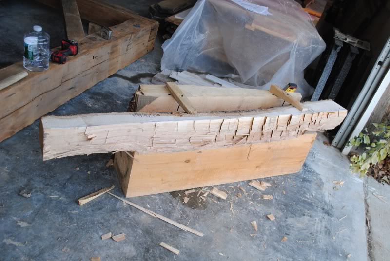 Dutch inspired trestle. I was having trouble repairing braces and studs from my Dutch barn project. Horses just walked around when I tried to chop or pare. With the trestle, there is no wiggling at all. It's six feet long, so very short pieces I clamp across just one end. 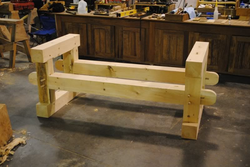
Member, Timber Framers Guild
|
|
|
|
Re: Shop Project
#25798
03/05/11 06:08 AM
|
Joined: May 2010
Posts: 946
D L Bahler
OP
Member
|
|
OP
Member
Joined: May 2010
Posts: 946 |
NH, thanks for the heads up. I know it's not going to be easy, but that's not the point is it! This isn't my first hewing experience either, so I know what's ahead of me. I am concerned though that after this winter my callouses aren't as thick and my hewing muscles are a bit out of shape. I was hewing the other day, and just got tired too fast! Guess it's time to get back in the swing of things again!
I do try to make a habit of wearing leather gloves when I hew, and usually some kind of gloves when working with most large hand tools.
I'd like to come up with a trestle sort of assembly that I can use to clamp things securely without using clamps, I've got an idea for a way to do it with friction wedges, may be I'll draw it out in the morning and see how it looks.
I've also got an idea to make a head clamp, which is just a way of securing a timber or log on one end with a massive weight, with the bulk of the piece or a sizable portion of it anyway hanging freely, allowing you to work at most of it unhindered by stands or tables. It is in a way kind of like a gigantic shaving horse head. This of course would not be a very mobile tool!
I also have a mind to go cut some poles and put up a pavilion to use as an outdoor shelter for my layout and cutting. That would further increase the traditionalism of the whole thing, and also keep valuable shop space free and clear. To keep it from becoming a mud hole, I might cover the ground (once the grass is worn off) with a good coating of ag lime.
I'm gonna go timber huntin tomorrow, maybe find some trees that would suit my needs. Though I am certainly hesitant to cut them in the spring. Likely I'll just mark them for future cutting. I've got a few down and some dead standing that should keep me busy at least till mid summer.
I'm more or less being a scavenger on this project, huntin high and low for any timber I can get my hands on!
DLB
|
|
|
|
|