Joel, that makes me feel good but I'm certainly out of my league. Surely we can find a more knowledgeable writer on the merits of Christmas cookies

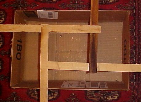
Thane, that picture must have been taken during the unbalanced loading portion of our testing. But yes, this is far from scientific or exhaustive. I did try to distribute my load on it better this morning.
I've been doing some reading in the links Mike posted, try this on for size. In a flat reciprocal frame, what Mo introduced this thread with, a grillage floor system, the members have no axial load, they experience only bending. The math I used above should be a fair fit for that situation. This is a model of grillage floor beams atop walls, they could be joined together in one flat plane.
As soon as the members begin to incline they begin to act partially as a column and partially as a horizontal beam. Take the cosine of the rafter angle and multiply it by the load. I think it would yield the bending load. The rest is travelling down the rafter as an axial load.
As an example if the rafters in my model were 20 degrees from horizontal;
Cos(20)= .94, so 6% of the load is axial and 94% of the load is bending the rafter
Now stand them up more
Cos(45)=.71, 29% of the load is carried by the beam as a column and 71% of the load is causing bending.
Getting closer to reality?


