"The theory behind the long slanted bracing in German building styles is that a brace to a post compromises its integrity, so the braces here join to the sill and the top plate. This results in a lack of any triangles, so rather than relying on the immutability of the angles of a triangle to maintain squareness of the walls, we are relying on the fact that the brace has to stand upright for the walls to shift."
I think I understand the concept, now, which makes it a lot easier to visualize how my design should proceed. The purpose of this system is to reduce the vertical/diagonal structures composing the wall into purely tensile/compression load paths, which resolve into point loads & moments along the horizontal plates (which from what I can tell are themselves among the more beefy structural elements, often composed of an upper & lower beam sandwiching the floor joists).
Makes a lot of sense from a load-efficiency standpoint, since vertical wall elements are typically long & lanky, therefore ill suited to carrying moments specifically (though not so long as to buckle under compression loads with even modest stabilizing braces along their length). Likewise, the horizontal plates only span between posts, which is far shorter a distance than the height of each story, and are very rigidly attached at these points, the result being far less deflection for a given moment. Seems inherently stronger for a given timber size than shorter (stiffer) braces at 45deg angles that terminate in the middle of the posts. I have noticed that a lot of the traditional Riegelbau frames seem to use similar-looking sharp angled diagonals, but break the wall into a tight grid with more frequent horizontal members --I presume this is to break up a daub-style infill into more manageable chunks?
So I suppose the tactic is to design the walls as though the columns are masonry (i.e. no bending, no tension), the diagonal braces steel rod (tension/compression only), and treat the floor as 'rigid' for all intents & purposes (reinforcing it as needed to get its loads to acceptable levels later on in the design)
" Also, "oblique bracing" modalities also function better in the "buttressing context" (i.e. at the base of a post) and can also work very well in the "horizontal" configuration within floor and roof systems as well. (i.e. "strong back" and "dragon beam" systems)"
Dragon beam as a floor support? Color me interested, I thought it was a roof-only thing (and Google search for 'Dragon Beam' helpfully yields mostly fantasy-art featuring reptiles). Since I have an octagonal floorplan, the typical rectangular joist/support systems don't seem like they will fit nicely, but a dragon-looking angled junction coming in to cover triangular areas seems feasible; any good examples of a floor structure done this way?
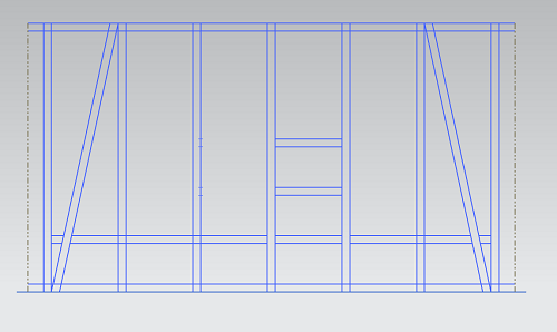
This is a rough sketch of how I'm laying out my walls; this is a single 20ftx10ft side of one floor of the structure
-4X's are pictured, but I'm mostly just laying out locations here
-33" centers*
-Top plate rests between the inner/outer posts on the tie-bars
-Diagonal members sit between the posts, joined to both plates (they would be entirely hidden by the plank-based infill I've proposed)
-Dashed lines at the ends are where the wall panels meet; horizontal members will be lap-jointed for attachment
-The short horizontal intercostals are for attaching (non-structural?) interior walls where needed --aircraft-style)
-The long horizontal member is that intermediate sill which forms the internal routing path for utilities
*Since such a simple sketch doesn't convey much information on its own, I wanted to explain my approach a bit more. My goal is to create a 'wall plan' that is adaptable to the other fifteen walls (down to 'interchangeable' beams), and can be easily tailored for the various doors/windows/walls that lie on it. I figured that if I get a good solid structural box at the sides, I'll be able to more freely remove, shift, and replace the structure between the second posts from each end as desired --being octagonal, each of those boxes will tie to an adjacent wall to form a ~5ft wide shallow-V-shaped column at the corners. So for the north-end of the structure with a second floor to support, there will be more posts to carry floor joists, whereas the south-facing side with only a narrow cantilevered walkway inside & outside can be pierced by good-sized windows along with the second floor.
I plan to analyze the structure with
none of the intermediate framework between the second to last posts present; wherever loads show deficient, I'll go back and verify whether or not the posts in the middle pick up the slack, or if the posts/plates need to be beefed up to get below acceptable limits. Think of the building like two Gazebos stacked on eachother (
hey, that's a cool idea)
TCB


